


Patents Completed.
Page 22
If you've noticed an error in this article please click here to report it so we can fix it.
Another Two-cycle Engine.
C. T. B. Sangster and W. Evans.— No. 9056, dated 11th April, 1911.—In -this engine a trunk piston of two diameters is need, and the annular space -around the smaller diameter at the lower end of the piston is utilized as a pump chamber. Mixture is admitted by the valve on the right-hand side to this -annular chamber during the up-stroke of the piston, and this mixture is compressed on the down-stroke, finally escaping by means of vertical grooves formed in the cylinder wall to the upper sid,, of the piston where it may be deflected in any direction by the suitably shaped piston, and so assist in expelling the ex haust.
A Heavy Oil Carburetter.
J. W. Mowbray, No. 16,048, dated 11th July, 1911.—This specification dc. scribes a carburetter for heavy oils wherein the fuel is first mechanically atomized and the mixture then heated to complete tbe vaporization. Fuel is supplied to a small reservoir provided with an overflow to keep a constant level. It .passes thence by way of a controlling needle-valve to a horizontal passage which opens into a flared combining tube provided at its further end with a .spring-controlled flat valve. A conical valve carried by this flat valve closes the .end of the horizontal passage, but opens it when the flat valve is lifted off its seat. Surrounding the nozzle, and the combining tube, is a cage-work, whereby the air is admitted during suction. The inward passage, and the expansion of the air in the flared combining tube, draws fuel out of the jet, and projects it against the conical nozzle, whereby it is atomized and carried with the air past the flat valve into a heating chamber which is preferably heated by the exhaust gases. Arrangements are made for injecting a small quantity of water into this chamber to mix with each charge which then passes by way of the throttle of the cylinder inlet.
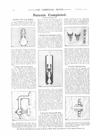
A Simple Fuel Admission Valve.
A. B. Breuer.—No. 10,365, dated 28th April, 1911.--This specification describes a valve for internal-combustion engines adapted to operate with liquid fuel, and more particularly to valves adapted for injecting the fuel into the cylinder or combustion chamber of the engine when a considerable degree of compression exists therein. The object of the inven
tion is to provide a valve of this kind which shall be eimple and readily adjustable, and shall completely vaporize the fuel with a lower air pressure than is at present required. The valve controlling the flow of the oil is provided with a central 'passage through which the air passes and which is controlled by a separate valve secured in a casing on the top of the oil valve. Some lost motion is provided between the two valves so that lifting the air valve spindle first opens the air passage, and on further movement engages the casing and opens the oil-valve so that there is a flow of air through the nozzle before the oil begins to flow.
A Sectional Detachable Rim.
J. W. Hall and C. Baynes, No. 9281, dated 13th April, 1911.—This specification describes a detachable rim for resilient tires which enables the rim to be placed in position when the tire is fully inflated or otherwise. The rim is divided into, say, four segments, each of which is provided with a number of feet which have inclined surfaces leading up to a surface which is approximately
parallel with the rim section. The felloe of the wheel carries a circumferential band formed with an outstanding flange on one side, and there are situated at intervals radial slots each provided with a sleeve through which passes a security bolt entering a security pad which engages the rim and tire. A hole for the valve is provided in one of the sections, and preferably a driving stop is formed adjacent to it to give a positive connection between the felloe and the rim, and to take any driving strains off the valve tube. The section views of the wheel show, on the left, the rim in position but not driven home, and in the centre the final adjustment of the rim on the wheel.
A Fowler Driving Gear.
R. H. Fowler, W. T. Lalonde and G. S. Tuer, No. 726, dated 9th January, 1912—In road locomotives carried on springs, provision must be made for ensuring continuous engagement of the toothed wheels of the driving gear which have relative motion owing to the play of the springs. According to the present invention, this is obtained by the construction illustrated wherein the driving spur-wheel is provided with internal and external teeth, and is carried on a hollow boss, the wheel being driven from the crankshaft. The bearing for the third motion shaft can slide up and down within this boss, and the pinion keyed on this shaft is provided with two sets of teeth, one of which is of nearly the same pitch diameter as the internal teeth on the driving spur-wheel and engages
with them ; the other set of teeth engages with the gear-wheel on the driving-axle and is kept in constant relation therewith by a radius rod.