


The compression ignition engine, 8
Page 64
If you've noticed an error in this article please click here to report it so we can fix it.
When a fuel injection pump on a compression ignition engine is replaced, if the system has been opened for any reason (eg, to fit a new fuel filter), or if the vehicle has run out of fuel, air will have entered the system and it will be necessary for this air to be expelled before the engine will run satisfactorily.
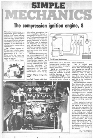
Fig 1 shows a diagram of a DPA pump and injection system with the venting or -bleed" points lettered A, B, C and D. Before venting the system the vent screws and the union. nuts need to be operled.
The fuel lift pump has a priming lever which allows fuel to be pumped from the tank by hand without the engine turning over. The filter outlet connection or the injector pump inlet connection, depending on which is the highest, must be slackened and the priming lever operated until fuel escapes from the slackened connection without being mixed with air bubbles, when the union may be retightened.
The vent screws on the pump are now slackened and the priming lever again operated, tightening the screws when all the air has been expelled. Two union nuts at the injector ends of the high pressure pipes must now be slackened. The accelerator is set at the fully open position, the "stop" control put in the "run" position and the engine turned with the starter. When fuel oil, free from bubbles, issues from both injector pipes the engine is ready for starting and running.
Fig 2 is a photograph of a BMC diesel engine and clearly shows the pipework, lift pump and filter discussed in the previous paragraph. Fig 3 is a close up of a DPA pump on which the two venting screws referred to above can be seen.
Care is needed wher removing injectors from cylinde heads. After disconnecting thi high pressure fuel line and thi leak off pipe and unscrewing thi retaining nuts, it may bi necessary to prise the inject° out. Care must be taken ti maintain an equal pressure or each side so that the injector withdrawn evenly.
A copper washer is generall fitted between the injector anE the cylinder head. It is importan that this washer is not lost, es pecially if the work is being don( at the roadside where it is no possible to obtain a replace ment. The washer ensures 2 sound thermal joint between thi injector and the cylinder head al well as providing a gas tigh seal.
When replacing injector: care must be taken to see tha the washer is an easy but no loose fit on the nozzle body. Th( nozzle holder must be an easy fi in the cylinder head tunnel an( on the holding down studs s( that it can be placed in positiol without force of any kind, If thE nozzle end seems tight in thE cylinder pocket, the pocke should be cleaned out with 2' piece of hardwood. ThE securing nuts should be ugh tened down evenly in order t( prevent the nozzle tilting ove and jamming.
by Preceptor