


ew Equipment Silences
Page 39
If you've noticed an error in this article please click here to report it so we can fix it.
" Diesel Knock
At Least One British Maker to Fit Swedish Device to Control Fuel Supply During Pump Injection Period HIGH-SPEED oil enginos are noted for their characteristic knock, which is caused by the rapid pressure rise in the combustion chamber. How to overcome this objectionable noise has been a Problem which has faced engine and injectionequipment technicians since the inception of the high-speed compression ignition engine.
It was recognized that some form of two-stage injection was required, but how to achieve this without employing two fuel pumps set at differential timings was the task presented to the technicians.
The Atlas Diesel Co., of Stockholm, approached the problem by designing equipment consisting of a two-stage cam and a special two-stage injector. This has recently been adapted experimentally to a popular make of engine in this country and is at present undergoing extensive operational tests in a bits chassis.
Offers Increased Engine Life
There is no doubt that "Diesel knock" is eliminated, because when demonstrated to a representative of "•The Commercial Motor," the tappet noise was heard above all other noises when the engine was operating at any speed. In addition to quietening the noise, the system, because of its lower pressure rise, offers longer operational life to the engine, The excessive pressure rise of the orthodox system exposes the pistons, connecting rods, bearings, crankshaft, crankcase and other parts to a violent shock loading. Using the Atlas injection equipment, it may be possible to produce engines which will be lighter in construction, thus giving a higher power-to-weight ratio.
Basically, the Atlas two-stage system provides continuous fuel injection. The first part is made at a low fuel speed and pressure, and is directly continued at the latter stage, where the fuel pressure and speed are increased. Because of the low injection rate of the early period, the quantity of fuel present in the combustion chamber when ignition occurs is so small that the pressure rise on combustion is insufficient to create knock or violent stressing of the engine parts.
With the high temperature built up in the cylinder by the first stage of combustion, fuel injected later burns successively as it enters the cylinder. The cam in the injection pump is designed to start pumping from the base circle and the first contour, with a rather moderate shape, gives a relatively low and nearly constant injection pressure.
This is followed by the second stage of injection, where the cam has a relatively sharp slope, giving an injection pressure that is increased successively
to. its maximum value. The joint between the two contours is made with a smooth curve and is shaped so that injection is not interrupted between the two periods.
Two-stage Injector
Ti was necessary to design a special injector nozzle so that, although operating at a low pressure, the fuel would be correctly atomized and there would be no "after-dribble.' In addition to the normal requirements, the injector had to be designed so that its closing pressure would be higher than its opening pressure, thus giving a sharp cut-off at the end of the injection.
The difference between the comparatively low opening pressure and high closing pressure is solved in the construction of the nozzle, which is
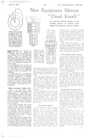
provided with two separate annular spaces around the needle, in which fuel pressure can act upon the needle in the opening direction. The upper space is in direct connection with the delivery pipe, but the lower space is separated from the delivery pipe by small nonreturn valves which are coupled in parallel.
These valves close against seat towards the upper annular space and are spring-loaded in that direction. the function of these valves is to prevent the combustion pressure from pushing fuel in the nozzles back into the delivery pipe at the end of the injection.
Low-pressure Main Spring In operation, when the pump begins delivery to the injector, the fuel passes directly into the upper annular sp.ice and, by way of the non-return valves, into the lower space. Thus, in the opening moment, the fuel pressure acts in an opening direction in both annular spaces. This enables the main spring in the injector to be set at a low pressure, and the injector is set to open at 70 to 75 atmospheres.
At the end of injection the fuel pressure in the pump and delivery line falls suddenly. The non-return valve in the injector closes rapidly, leaving the main injector spring to overcome the pressure from only one of the annular spaces. By this means it is possible for the spring to close the needle valve against a much higher fuel pressure than that required to open the valve initially.
Cutting Out Pressure Waves With the sharp fuel cut-off from the pump and unloading of pressure from the delivery pipe, pressure waves might be set up in the pump to disturb injection of fuel to the other cylinders. the Atlas Diesel Co. has produced it patented delivery valve which meters fuel back into the pump and controls the unloading of the pipe line in such a manner that no pressure wave is set up to disturb the injection to other cylinders or cause dribble at the injector nozzle.
Much experimental research and development have been necessary to obtain perfect liaison between the twostage cam, delivery valve and injector, all of which is described in a paper entitled "The New Atlas Diesel Fuel Injection System for Diesel Engines," which was read by Mr. T. H. Pyk, M.I.Mar.,E., chief engineer of the A.B. Atlas Diesel Co., at a meeting of the Institute of Marine Engineers held in London