


Novelty in Brake Design
Page 60
If you've noticed an error in this article please click here to report it so we can fix it.
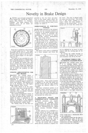
A NOVEL type of brake is described 1--/, in patent No. 739,590 (K. Mikkolainen, Hat Valtatie 12, Tampere. Finland). The brake employs four separate shoes, all of which are expanded in unison.
Each shoe is guided by a slot working on a fixed anchor pin (I). The single operating cam (2) can be turned about the axle, and is made to do so by gear teeth (3) which couple it to the operating lever (4).
Two lobes (5) are provided for each shoe; although shown as rubbing faces they would -preferably be rollers. The act of turning the central cam thus thrusts all four shoes into action simultaneously. By 'cutting the anchor-pin slots at an angle to the radius, the brake can be given the property of selfenergization.
COOLING ARRANGEMENTS FOR• , DISC BRAKES D ATE N T No. 739,244 shows a
scheme for cooling disc brakes by injecting water. Whilst the scheme is illustrated as applied to aeroplane 'wheels, it would be equally suitable for heavy road vehicles. The patentees are the S. K. Wellman Co., 200 Egbert Road, Bedford, Ohio, U.S.A.
The brake shown is of the multidisc type, using three moving and four stationary discs. They are put into operation when an annular hydraulic piston (1) is pressurized.
The cooling arrangements consist of a water inlet (2) which is ported to the space in which the discs work. The supply of water is controlled by the degree of braking; if the hydraulic pressure rises above a certain figure a valve automatically admits water.
The mating faces of the discs are grooved so that the water can penetrate to the actual region where the heat is generated. The water does not return; it is converted into steam which escapes via outlets 3.
IMPROVEMENTS IN INJECTION NOZZLES INJECTORS operated by the pressure I of the fuel are extremely sensitive to variations in the applied pressure and a design claimed to minimize this sensitiveness is disclosed in patent No. 738,360 (Texaco Development Corp., New York, U.S.A.).
The drawing shows an enlarged view of the tip of the nozzle. The pintle (I) is spring-loaded in an upwards direction and seals on the coned seating 2. As soon as the pintle is unseated by the pressure, fuel flows down the clearance and emerges through a narrow annular gap (3) The pintle at this point is cylindrical for a short distance and forms the imiting orifice. When greater pressure is applied by the fuel, the pintle can descend further until the taper portion (4) causes the effective orifice to be enlarged.
The short cylindrical portion is an important feature .because it is said to prevent the pintle from chattering on its seat; this is due to the fact that over a short range the pintle movement does not increase the orifice area.
A MEASURING DEVICE FOR OVERHEAD-VALVE CLEARANCE
VALVE clearances are usually measured by pushing feeler gauges between the parts, but a better method is shown in patent No. 739,437 (P. and G. Manufacturing Co., 2262N Albine Avenue, Portland, Oregon, U.S.A.).
A dial indicator (1) is attached to a tubular column (2) which is cut away so that it can clear the valve and make contact with spring collar 3. Sliding inside the column is another tube (4) biased upwardly by a spring. A small foot at the bottom of this tube is arranged to hook under the rocker.
To use, the central tube is pushed down and the assembly is slipped over
the valve. The foot is placed under the rocker and then let go. The central part is thus firmly coupled to the rocker, whilst the outer member 'is butting on the spring collar. A projecting arm (5) from the central part can be adjusted by its screw to make contact with the moving part of the indicator.
By moving the rocker through its clearance, the distance can be easily and accurately read off on the dial.
HEATPROOF THROAT FOR ALUMINIUM CYLINDER HEAD
PATEN T No. 735,834 comes from S. A. Adolphe Sauer, Arbon, Switzerland, and refers to two-stroke oil engines employing aluminium alloy for the cylinder head. In such heads, the problem of heat erosion is a serious one, and the patent deals with a means. for eliminating or reducing it.
The drawing shows a section of an' engine with its light-alloy head (1). The combustion chamber (2) is formed in the head and leads to the cylinder space via a narrower bore (3). This thin edge is the part that suffers heat damage.
It is proposed to insert a ring (4) of some heat-resisting material. Ordinarily, a nickel alloy would be chosen, but it has the disadvantage that its heat con ductivity is low. This means tllig it would reach a very high temperature, which would have a detrimental effect on the combustion.
The material chosen for the ring is a wrought-aluminium alloy of the type known as Y alloy. This has the same conductivity and heat expansion as the metal of the head, but is stronger.