


A NEW STEERING SOcKET.
Page 26
If you've noticed an error in this article please click here to report it so we can fix it.
A Résumé of Recently Published Patents.
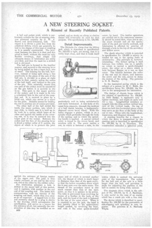
A ball and socket joint, whirls is particularly suitable for use on steering rods, vas patented recently by G. W: A. Brown and Arrol-Jehuston, Ltd. The object is to devise a joint free from the admitted defects which can generally be laid to the charge of this type of coupling as it is usually constructed. The principal features are that it is dust and dirt proof in itself, without the need for ugly flexible coverings, that simple and adequate means of lubrication are easily provided, and that the need for a Blotted Tod is obviated. .
The ball pin is formed in the familiar manner, and secured to the steering lever by being pulled up into a taper lime, also as usual. The bearing for the ball, however, instead of being split along a line practically in the plane of the axis of the ball pip, is divided in a plane at right angles to that, namely, across the centre of the ball itself, and vertical to the axis of the pin.. This, naturally, means that one part-of the socket must be assembled on the pin before it is secured in the lever. This part is the major portion of the socket, and it is made to fit into a cylindrical hole in the end of the coupling rod. It is secured in place by a blind nut, which also serves as a coyer for the joint. Suitable means for locking the nut in position are of course provided. The other half of the ball socket fits inside the major portion, into which it may slide, in which case it is held up to its work by a spring which bears at its other end against the inside of the covering nut, or it may be screwedinto the larger part of the socket. Between the socket and the face of the steering lever is fitted a rubber collar of U section, the object of which is to protect the joint
against the entrance of foreign matter at the upper end. The joint is thus totally enclosed, at one end by the cover nut and at the ether by the rubber collar.
For lubrication purposes a hole is drilled in the major half of this socket, and it registers with another in the eye end of the coupling rod. The latter hole communicates with the interior of the coupling rod itself, which thus nees day as ari oil reservoir.. A tapped hole in the rod normally closed by a plug is shown in the drawing which accompanies the specification, and serves as a means for the entrance of oil, but naturally the construction of this may be modified -as re
B52 quired, and no doubt am alien') or or similar means will eventually be used for that purpose. The specification is No. 134,709.
Detail Improvements, The Michelin Co, claim that the lifting jack which is described in specification No. 125,072 is light, yet strong, that it is easily kept clean, and that it lends itself particularly well to being satisfactorily and easily lubricated. A cast body. of the usual form supports, through the medium of a ball thrust bearing, a hoiizentallydisposed crown bevel wheel. With the latter engages a pinion, which is on a spindle which protrudes through the body of the casting, and to -which the operating handle is applied. A central vertical screw ie keyed to the crown bevel, and revolves with it. The screw carries a nut, to which is fastened a tube, in the upper end of which is secured another nut., the thread of which is much larger in diameter than that of the wain screw, so that the hollow secondary screw which fits it may pass over the main screw. The thread of the secondary screw is also much coarser than that of the mail. screw, so that it is quicker in its action. The tube is prevented from revolving by means of a feather in the body of the jack, and the head of the jack is fastened to the top of the outer screw. When it is required to use the jack, the head is first quickly lifted to the approximate height needed, by revolving the head, and with it the outer quick-threaded screw, by hand. The further aperations arc carried out in the customary manner. It should be noted that, when not in use, the screw threads and all the mechanism of the jack are totally enclosed, and lubrication is effected by pouring oil through a hole in the top of the secondary and hollow screw.
The shock absorber which is patented in specification No. 134,603 is mainly intended for use in the spring forks of motorcycles. The principle is, however, interesting. The helical spring is held between two collars, one on a spindle on which is turned a quick-threaded
• screw, the other on a sleeve which is held between flanges on a nut on that screw. The friction between the collar of the nut and its sleeve, and between the screw and the nut, serves to damp the motion of the spring. -The patentee is G. E. Stanley.
In the laminated spring which is the subject of a patent by R. C. Robb, the specification being No. 134,604, the feature is the arrangement for lubrication.
. The design of chassis frame which is the subject of specification No. 134,660, by John Budge, is applicable only to lighter machines, and might do quite well for a van. Longitudinal_ members arranged with the eeep section vertical take care of the vertical loads. On. top of them are laid thin horizontal pieces which may serve as the floor of the body of the car or van.' These take the longitudinal, transverse, and diagonal stresses.
A steering knuckle for a chassis in which the drive is transmitted by the steering axle is described in specification No. 134,706, by A. A. Thornton. The construction embodies a spherical joint, within which is centred the universal joint of the transmission. The socket for the ball end of the axle is a little larger than the ball, and provision is made for adjusting the position of the ball to ensure its being truly central.
The magneto drive which is the subject of No. 154,712, by G. J. Rackham, is only useful in the case of an engine . which has a crank pin with a free end.
The device which is described in specification No. 134,763 for the prevention of side-slipping and splashing is very ingenius. The patentee is A. :MacLean Whyte.