


Patents Completed.
Page 40
If you've noticed an error in this article please click here to report it so we can fix it.
Improved Epicyclic Gearing. Pneumatic Tire Valves. A New Carburetter. Friction Levice for Preventing Vibration.
Copies of complete specifications of the patents published on this pare can be obtained from the Sales Branch, Patent Office, Holborn, W.C., at the cost of sixpence for each specification.
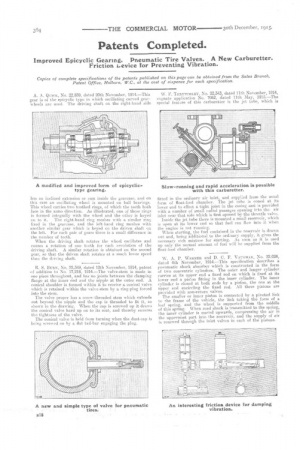
A. A. Qctex, No. 22,839, dated 20th November, 1914.—This gear is of the epicyclic type in which oscillating curved gearwheels are used. The driving shaft. on the right-hand side
has an inclined extension or cam inside the gearease,. and on this cam an oscillating wheel is mounted CM ball bearings. This wheel carries two toothed rings, of which the teeth both face in the samo direction. As illustrated, one of these rings is formed integrally with the wheel and the ether is keyed
on to it. The right-hand ring meshes with a similar ring fixed in the gearcase, and the left-hand ring meshes with another similar gear which is keyed an the driven shaft on the left. For each pair of gears there is a small difference in the number of teeth.
When the driving shaft rotates the wheel oscillates and causes a rotation of one tooth for each revolution of the driving shaft. A similar rotation is obtained on the second gear, so that the driven shaft rotates at a. much lower speed than the driving shaft.
R. S. ButtN,.N.a. 22,389, dated 12th November, 1914, patent of addition to No. 17,218, 1914.—The valve-stem is made in one piece throughout, and has no joints between the clamping flange at the inner end and the nipple at the outer end. A conical shoulder is formed within it to receive a conical valve which is retained within the valve-stem by a ring-plug forced into the stem. .
The valve proper has a screw-threaded stem which extends nut beyond the nipple and the cap is threaded to fit it, as shown in the drawing. When the cap is screwed up it draws the conical valve hard up on to its seat, and thereby ensures the tightness of the valve.
The conical valve is held from turning when the dust-cap is being screwed on by a flat tail-bar engaging the plug.
W. F. THRUTCHLEY, No. 22,343, dated 11th November, 1914, cognate application No. 7062, dated 11th May, 1915.—The special feature of this carburetter is the jet. tube, which is fitted in the ordinary air inlet?, and supplied from the usual form of float-feed chamber. Ihe jet tube is coned at its lower end to effect a tight joint in the casing and is provided with a number of small radial passages opening irto the air inlet near that side which is first opened by the throttle valve.
Inside the jet tube there is mounted a small reservoir, which is open at its lower end so that fuel can flow into it when the engine is not. running.
When starting, the fuel contained in the reservoir is drawn out and, being additional to the ordinary supply, it .gives the necessary rich' mixture for starting. As soon as it is used up only the normal amount of fuel will be supplied from the float-feed chamber.
W. A. P. WERNER and D. C. F. Vatenexx, No. 22,024, dated 4th November, 1914.—This specification describes a pneumatic shock absorber which is constructed in the form of two concentric cylinders. The outer and longer cylinder carries at its upper end a fixed rod on which is fixed at its lower end a piston fitting in the inner cylinder. The inner cylinder is closed at both ends by a piston, the one at the upper end encircling the fixed rod. All three pistons are provided with non-return valves. The smaller or inner piston is connected by a pivoted link to the frame of the vehicle, the link taking the form of a leaf spring, and the wheel is supported from the middle of this spring. When road shock is transmitted to the spring, the inner cylinder is moved upwards, compressing the. air in the uppermost part into the reservoir, and the supply of air is renewed through the inlet valves in each of the pistons.