


A Machine for Hardening Camshafts
Page 48
If you've noticed an error in this article please click here to report it so we can fix it.
A Resume of Recently Published Patent Specifications
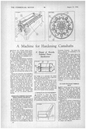
PATENT No. 577,044, which comes from J. Swan and the Ford Motor Co., Ltd., 88, Regent Street, London, W. I, gives details of a machine designed for the hardening of camshafts on a production-line basis.
The machine will hold four camshafts in varying stages of treatment. At each end is a four-armed spider (1) rotated by a Geneva mechanism (2) which iinpagts an intermittent motion in the well-known manner. A camshaft is placed by the operator in the position indicated by 3; it is then moved over to the other side, where a row of oxycoal-gas jets (4) heats the surface of the cams.
During this operation, the camshak is revolved on its own axis by means of planet pinions (5). After a timed heating, the shaft is moved on and is quenched by being taken into a tank of liquid at the bottom of the machine. Upon emerging from the tank, the camshaft returns to the first position in which it is removed by the operator and replaced by another one, so that the whole process proceeds continuously.
As an alternative to the flame-heating method mentioned, the patent also covers the use of electric induction heating.
REMOVING FOREIGN MATTER FROM ENGINE BEARINGS
ASCHEME by which the bearings of an engine can be continually cleared of small particles of worn-off metal is shown in patent No. 576,991, by
Overland Motors Inc., Toledo, Ohio, U.S.A. The scheme is stated materially to lengthen the life of engine bearings by eliminating scoring.
The lutiricating system employed is the standard pressure-fed type in which the oil is pumped to a concentric groove 'cut in the main bearings, whence it reaches the big-ends via drilled passages in the crankshaft. In the present scheme, however; the main-bearing groove (1) is not a complete circle, but is blocked by a small bridge (2). Beyond the bridge is a vent-hole (3), which passes the bolt and provides a lead into the crankcase from point 4.
In action, the groove functions in the usual manner for most of the circle, but when the crankshaft oilway passes over the bridge-piece, the pressure is cut off. Further rotation momentarily opens the oil assages to the vent, and any small particles can thus escape and fall to the bottom of the crankcase.
A NOVELTY IN CLUTCH DESIGN
ACLUTCH in which the friction member is arranged rather like a brake-shoe instead of in the form of a disc, is shown in patent No. 577,325, by P. Lombardini, Stockley Burn Cottage,
Frosterley, Darham. The clutch also gives a measuie of cushioning to the transmitted torque.
In this scheme the engine drives the inner member, whilst the outer casing is connected to the output shaft. The friction member consists of a flanged ring (I), which is a running fit in the external casing and can be expanded into driving contact therewith by the outward movement of five tappets (2). These are simultaneously operated by a pyramid-shaped central shaft which slides in or out under the control of the driver's pedal. Each tappet is provided with a pressure Spring (3) and a pair of torque-springs (4)_ The friction ring is arranged to be slightly e‘centric with respect to the casing, but the reason for this is not stated. The clutch is intended to run in oil, and provision is made for the oil to reach the rubbing surfaces.
AN EASY-TO-CLEAN VEHICLE SEAT NiTOST vehicle seats have,at least one alportion attached to the framing, which means that the operation of cleaning is less satisfactory than it could be. A seat in which all the upholstered pieces are readily detachable for cleaning is shown in patent No. 577,424, by R. Hicks, and Beresford and Hicks (Bedding), Ltd., 131-139, Curtain Road, London, E.C.2.
Although the scheme is illustrated as applied to a single car-seat, it is stated to be equally applicable to the larger sizes as used in buses and coaches. The chief feature is that the cushion and back pieces are made as separate members, and each is mounted on its own squab frame. The latter is made of thin sheet steel, supported by extra steel strips used after the manner of webbing. rhe seat and the back are attached to the framing by a quick-release fixing, and the two pieces are united by a simi tar arrangenient; in this case a series of rings (1) is used. The design seems to be simple and effective.