


SEEKING THE IDEAL I PISTON SHAPE
Page 32
Page 33
If you've noticed an error in this article please click here to report it so we can fix it.
A New Scrivener Machine for Piston Grinding Aims at Translating Theoretical Considerations into Practical Possibility
THE varying rates of expansion of pistons in internal combustion engines, present many interesting problems to designers, engine makers, the manufacturers of grinding machines and to vehicle users.
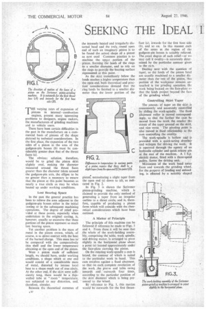
There have been certain difficulties in the past in the manufacture on a commercial basis of pistons of the shape dictated by technical considerations. In the first place, the expansion of the two sides of a piston in the area of the gudgeon-pin bosses (b) must be considerably greater than that of the thrust faces (a).
The obvioto solution, therefore, would be to grind the piston skirt slightly oval, making the diameter measured around the thrust faces greater than the diameter taken around the gudgeon-pin axis. the ellipse to be no greater than is necessary to ensure that the piston at this point becomes as nearly a true circle as may be when heated up under working conditions.
Lost Bearing Space In the past the general practice has been to relieve the area adjacent to the gudgeon-pin bosses either in the initial casting or in the subsequent machining operations. The degree of relief provided at these points, especially when undertaken in the original casting, is, however, usually so excessive that these portions of the piston represent so much lost bearing space.
Yet another problem is the mass of metal in the piston crown. which,. of course, is m direct contact with the heat of the burned charge. This mass has to be compared with the comparatively thin shell and the lower temperature obtaining at the open end of the piston.
Were a piston made of sufficient length, we should have, under working conditions, a shape which at one end would consist of a considerable mass of metal, distorted by intense local heat to a shape much out of true circle. At the other end, if the skirt were sufficiently long, there would be a thinwalled tube at "room" temperature, not subjected to any distortion, and, therefore, circular.
Between the theoretical extremes of
the intensely heated and irregularly distorted head and the truly., round open end of such an imaginary piston is to be found the actual shape of a piston' as now used Common practice is to machine the upper portion of the piston, forming the lands of the rings to a smaller diameter, and to rely on the rings to provide the bearing surface represented at this point.
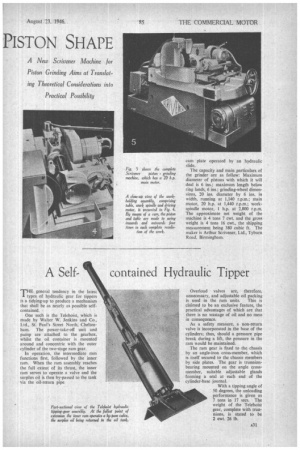
As the skirt immediately below the lands reaches a higher temperature than the open end, both theoretical and practical considerations demand that the ring lands be finished to a smaller diameter than the lower portion of the
pistort, necessitating a slight taper from the open end (c) down to (d), as indicated in Fig. 2.
In Fig. 5 is shown the Scrivener piston-grinding machine, which is claimed to provide the only method of generating a taper from an irregular outline to a direct circle, and is, therefore, capable of producing a piston form which will coincide with the theoretical considerations which have been outlined.
A. Matter of Principle
The principle of this machine can be followed if reference be made to Figs. 3 and 4. From these it will be seen that the whole of the work-holding assembly, comprising the table, work spindle, and driving motor, is arranged to pivot slightly in the horizontal plane about a point (a) located approximately under the face-plate carrying the piston.
On the rotating work-spindle a cam is keyed, the contour of which is suited to the particular work in hand. This cam revolves against a fixed abutment. so that on each complete revolution of the work the piston and table swing inwards and outwards four times, according to the particular position of the skirt diameter which is being presented • to the 'wheel:
By reference to Fig. 1, this motion would' be outwards for the first thrust
face (a), inwards for the first boss side (b), and so on. In this manner each of the areas in the region of the gudgeon-pin bosses is suitably relieved. The exact degree of such relief—or we may call it ovality—is accurately determined by the particular contour given to the cam.
Dealing next with the question of taper, as the lands of the piston head are usually machined to a smaller dia • meter than the rest of the piston, this portion of the vvorkpiece remains untouched in the grinding operation, the work being Incased on the face-plate so that the lands project beyond the face of the grinding wheel.
Controlling Skirt 'raper The amount of taper on the skirt is conveniently and accurately controlled by sliding the work-spindle. The fixed abutment roller is moved correspond ingly, so that the farther the cam be moved from the work the smaller the extent of the taper ground on the skirt, and vice versa. The pivoting point is also moved in fixed relationship to the cam controlling the ovalityi The work-spindle is hollow and is provided with is quick-acting drawbar and wristpin for driving the work. It is operated through the agency of an hydraulic cylinder and quick release pin at the rear of the machine. A I b.p. electric motor, fitted with a three-speed pulley, forms the driving unit.
Movement of the work head away from and towards the grinding wheel. for the purpor,e of loading and unloading, is effected by a suitably shaped cam plate operated by an hydraulic slide.
The capacity and main particulars of the grinder are as follow; Maximum diameter of pistons with which it will deal is 6 ins.; maximum length below ring lands, 6 ins.; grinding-wheel dimensions, 20 ins, diameter by 6 ins, in width, running at 1,140 r.p.m.; main motor, 20 h.p. at 1,440 r.p.m.; workspindle motor, 1 h.p. at 2,800 r.p.m. The approximate net weight of the machine is 4 tons 7 cwt. and the gross weight is 4 tons 16 cwt., the shipping measurement being 380 cubic ft. The maker is Arthur Scrivener, Ltd., Tyburn Road, Birmingham.