


Patents Completed.
Page 26
If you've noticed an error in this article please click here to report it so we can fix it.
A Novel Spanner. A F.I.A.T. Carburetter. Wolseley Back Axles.
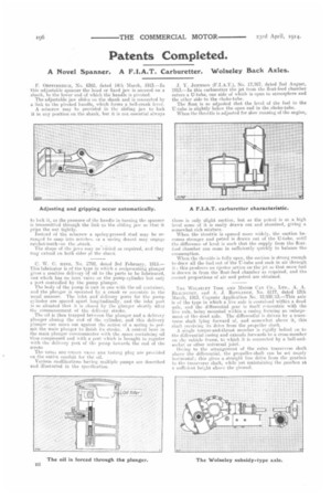
F. Orsrenrsercu, No. 6368, dated 14th March, 1913.—In this adjustable spanner the head or fixed jaw is secured on a shank, to the lower end of which the handle is pivoted.
The adjustable jaw slides on the shank and is connected by a Lek to the pivoted handle, which forms a bell-crank lever.
A setscrew may be provided in the sliding jaw to lock it in any position on the shank, but it is not essential always to lock it, as the pressure of the handle in turning the spanner is transmitted through the link • to the sliding jaw so that it grips the nut tightly. Instead of the setscrew a spring-pressed stud may be arranged to snap into notches, or a suing devent may engage ratchet-teeth-on the. shank.
The shape of the jaws may ne-vairied as required, and they may extend on both sides of the shank C. W. C. hINE, No. 2792, dated 3rd February, 1913.— This lubricator is of the type in which a reciprocating plunger gives a positive delivery of oil to the parts to be lubricated, an* which has no iniet valve on the pump-cylinder but only a port controlled by the pump plunger. The body of the pump is cast in one with the oil container, and the plunger is operated by a crank or eccentric in the usual manner, The inlet and delivery ports tor the pemp cyliuder are spaced apart longitudinally, and the inlet port is so situated that it is closed by the plunger shortly after the commencement of the delivery stroke.
The oil is then trapped between the plunger and a delivery plunger closing the end of the cylinder, and this delivery plunger can move out against the action of a spring to permit the main plunger to finish its stroke. A central bore in the main plunger communicates with the space containing oil thus compressed and with a port which is brought to register with the delivery port of the pump towards the end of the stroke
The unto non reternVe ana testing plug are provided on the outlet conduit, for the oil.
Various modifications having multiple pumps are described and illustrated in the specification. .T. Y. JOHNSON (F.I.A.T.), No. 17,767, dated 2nd August, 1913.—In this carburetter the jet from the float-feed chamber enters a U-tube, one side of which is open to atmosphere and the ether side to the ehoke-tube.
The float is so adjusted that the level of the fuel in the U-tube is slightly below the open end in the choke-tube. When the throttle is adjusted for glow running of the engine, there is only slight suction, but as the petrol is at a high level some of it is easily drawn out and atomized, giving a somewhat rich mixture.
When the throttle is opened more widely, the suction becomes stronger and petrol is drawn out of the U-tube, until the difference of level is such that the supply from the floaticed chamber can come in sufficiently quickly to balance the consumption. When the throttle is fully open, the suction is strong enough to draw all the fuel out of the U-tube and suck in air through it ; this produces an ejector action on the jet so that more fuel is drawn in from the float-feed chamber as required, and the correct proportions of air and petrol are obtained.
THE WOLSELEY TOOL AND MOTOR CAR CO., LTD., A. A. ReeeneoTote, and A. J. Rowramon, No. 6117, dated 12th March, 1913, Cognate Application No, 12,930,113.—This axle is of the type in which a live axle is contained within a dead axle, and the differential gear is itself concentric with the live axle, being mounted within a casing forming an enlargement of the dead axle. The differential is driven by a transverse shaft lying forward of, and somewhat above it, this shaft receiving its drive from the prepeller shaft.
A single torque-and-thrust member is rigidly bolted nu to the differential casing and extends forwards to a cross-member on the vehicle frame, to which it is connected by a ball-andsocket or other universal joint.
On ing to the arrangement of the extra transverse shaft above the differential, the propeller-shaft can be set nearly horizontal ; this gives a straight line drive from the gearbox to the transverse shaft, while yet maintaining the gearbox at a sufficient heiLlit above the ground.