


Patents Completed.
Page 26
If you've noticed an error in this article please click here to report it so we can fix it.
WHEEL GEARS.—Taylor and Another.—No. 18.421, dated 31st December, 1907.—According to this invention rotat
ing guards are provided for vehicle wheels. The guard -consists of a drum (d) mounted on a shaft (d2) carried by arms (b, be). These arms are provided with slots (13) and are adapted to slide in brackets /g) mounted on the vehicle frame. Bolts (e) are provided which pass through the slots in the arms (b, b2) to prevent their displacement. The drums (d) are held in frictional contact with the wheels of the vehicle by springs (k) arranged within the bracket CO and connected to the arms (b, be) at g3.
In a modification of this invention the rollers are rotated by means of spur gear and, in this case, are not held in frictional contact with the road wheels.
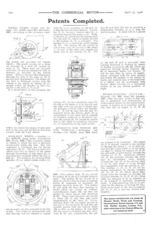
RESILIENT WHEEL. —Genillon. — No. 6,005/07, dated (under Convention) 19th March, 1906.—This invention relates to wheels in which the axle is mounted eccentrically within the hub. The hub comprises a cylindrical box (A) having side plates (K, J). The driving shaft (0), which transmits its motion to the wheel through the medium of side plates (K), is concentrically mounted within the box or hub (Ai. Two plates (e, d), carrying three spindles (T) on which double rollers (G)
are mounted, are also arranged in the hub or box. The rollers (G) are provided with ball bearings and are adapted to engage
with the inner periphery of the hub (A) so that the hub can rotate thereon. A member (Y, Z), having a vertical shot (X), is mounted between the plates (e, d). Within the slot /X), and below the driving shaft (0), the axle (El, which is rigidly secured to the member (Y, 2), is arranged. The member V. Z) is carriad by spiral springs (R, RI). The springs (R) are carried at one end by cups (S1 secured to the plates (r d) and, at the other end, engage the under side of the member (Y, 2). The springs (R1) are also carried by cups (SI) secured to the plates (c, d) at one end and the other ends are carried in flayed cups (II) arranged in holes within the member (Y, Z). It will be seen that the axle (E) mounted below the driving shaft (0) is independent of the latter and is capable of oscillation relatively to the shaft ; further, the springs (R, RI) absorb the shocks due to the wheel encountering obstacles On, or inequalities in the road surface.
APPARATUS FOR TESTING MOTOR VEHICLES.— Wellington and Another.—No. 10,018, dated 30th April, 1907.—Two endless belts (7) are carried by pulleys (6, 8) set at a suitable distance apart. The pulleys (6) are carried by a shaft (5) which is free to rotate in bearing blocks (3) supported by standards (2) suitably stayed to struts (4). The pulleys (8) and shaft (15) have their bearings in blocks which are carried by vertical, screw-threaded shafts (13) and they are guided by lattice braced steel structures (9, 10). These steel structures are carried in slides (12) so that they may move longitudinally to the base (11. Screwthreaded shafts (16) are rigidly secured at one end to the standards (2) and they are suitably geared with the vertical shafts (13) so that, as the pulleys (8) and shaft (15) are raised or lowered, the steel structures (9, 101 and, consequently, the pul leys (8) and shaft (15) will be moved in a longitudinal direction so as to keep the belt in tension. A motor vehicle is placed
on the belt (7( and is prevented from running backward or forward by means of flexible connections (28, 32) which are connected through spring balances (29, 31) to stationary beams (not shown). It will be seen that, by means of speedometers connected with the main pulleys and brakes (35) applied to the pulleys or shafts, any required data of the behaviour of a vehicle can be ascertained with facility whilst running on a horizontal surface or on any desired gradient or angle.
PETROL-ELECTRIC SY ST E M.— Mascord.—No. 608, dated 9th January, 1907.—This invention relates to that system of generation and transmission of motive power known as the petrol-electric system. A dynamo (a) is provided, and to this four sets of engine (b, bi, bt, are adapted to be connected. The engine set (b) is directly coupled to the dynamo• (a) through the pinion (e) on its shaft (d), and through a spur wheel (e) on the dynamo shaft (i), whilst the engines (bI„ 1)2, bs) are indirectly coupled thereto through the clutches (f, f1, f2). Additional clutches (f3, /4) are provided whereby the drive may 13.3 transmitted, when desired, tnrough the end (12) of the driving shaft Li) by the spur wheel (in being brought into engagement with the pinions (g, gl). The clutches (f, ft, f2, f3, 7'4) are actuated, respectively, by electric magnets vs, fb, fe, fd, fe) which derive their energy from the dynamo (a) through the solenoid switches (4, 41, 42, 43, 44); these latter are arranged to be so adjusted as to be actuated at gradually increasing loads. A plug-connecting box (1) is provided for the purpose of varying the electrical connections of the electro-magnets Ita, fb, fe, .f-1) to snit any desired combination.