


Electric Transmission for Multi-wheeled Vehicles
Page 64
If you've noticed an error in this article please click here to report it so we can fix it.
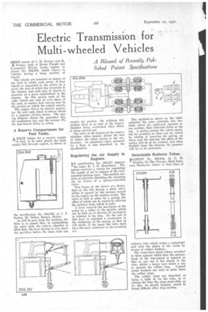
MEE names of C. 11. Fowler and H. Walker, both of Steam Plough and Locomotive Works, Leeds, appear in patent No. 354,808, which relates to vehicles having a large number of wheels.
The wheels are mounted on bogies of the kind in which each group of four wheels is supported in the centre by a pivot, the axis of-which lies crosswise to the chassis, and each pair of wheels is mounted on a pivot longitudinal to. the chassis. By this means each of the elght wheels can take an even share of the load, no matter how uneven may be the ground on which-the vehicle stands.
The engine drives an electric generator (h) and each wheel is driven direct by a separate electric motor. The -wiring diagram shows the generator (h), the conductors (g), and the motors (f), the last-named being in series.
A Reserve Compartment for -Fuel Tanks.
A NEAT. design for a reserve supply of fuel, to be used should the main supply fail through neglect, is shown in the specification No. 354,742, et C. Sutton, 19, Nelson Square, Bolton.
As will be seen from the drawing, the filler is so placed that, in replenishing the main tank, the reserve chamber is filled first, the lever having to rise above the partition before the main tank can receive its portion. By utilizing this method there is no fear of the reserve chamber being overlooked when filling is being carried out.
The valve at the bottom of the reserve chamber, when opened, allows the fuel to follow the .usual course to the carburettes. An automatic valve, actuated by a float, is also described in the specification.
Regulating the Air Supply in Engines.
IN specification No. 355,131 appears
the name K. J. E. -Resselman. The patent concerns a means for regulating' the supply of air to engines of the com-pression-ignition type. The method consists of partially throttling the incoming air by means of a spring-controlled
Two forms of the device are shown, that on the left having a clack valve, which is opened by the vacuum caused by the engine on the suction stroke. The valve is held in place by a spring, the effect of which can be varied by altering the position from which it pulls.
A lever controls the movement of the pump by a collar on the spindle, which can be held up to shorten its movement in relation to its cam. To the end of this lever is attached a connection to the anchorage of the spring, so that at full stroke of the pump the valve shall have the least resistance to the incoming
The applicatIon shown on the right embodies the same principle, but two clack valves are employed, opposed to one another, their fulcrums being at the top. A spring presses the valves apart, but its pressure on them can be varied by raising or lowering the spring, as when near the fulcrum the effort of the spring will be at its weakest, and when farthest from the fulcrum its pressure will be at its maximum.
Detachable Radiator Tubes.
pATENT No. 350,284, by C. H. Hughes, 18, The Terrace, High Lane, near Stockport, relates to that class of radiator tube which makes a watertight seal with the plates of the tanbs by means of rubber washers.
The tubes have metal collars attached to them against which bear the springs. Each of the last-named is tapered so that at one end it fits closely to the tube, whilst a larger part forms a cap to encircle the rubber ring. Conical metal washers are used to press home the rubber rings.
The rubber rings are described as being a tight fit on the tube, so to release the tube the rings must slide up it; this, we should imagine, would be found difficult after longservice,