


Three NEW BRISTOL
Page 51
Page 52
Page 53
If you've noticed an error in this article please click here to report it so we can fix it.
PASSENGER MODELS
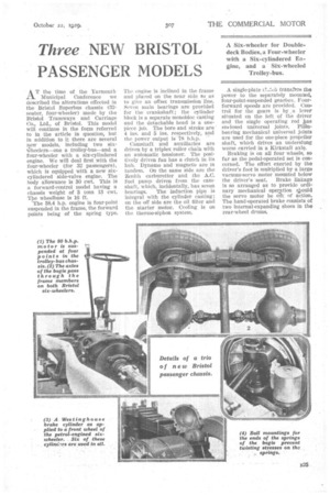
AT the time of the Yarmouth. Municipal Conference we described the alterations effected in the Bristol Superbus chassis (32seater, four-wheeler) made by the Bristol Tramways and Carriage Co., Ltd., of Bristol. This model will continue in the form referred to in the article in question, but in addition to it there are several iiew models, including two sixwheelers—one a trolley-bus—and a four-wheeler with a sit-cylindered engine. We will deal first with the four-wheeler (for 32 passengers), which is equipped with a new sixcylindered side-valve engine. The body allowance is 30 cwt. This is a forward-control model having a chassis weight of 3 tons 13 cwt. The wheelbase is 10 ft.
'The 38.4 h.p. engine is four-point suspended in the frame, the forward points being of the spring type. The engine is inclined in the frame and placed on the near side so as to give an offset transmission line. Seven main bearings are provided for the crankshaft; the cylinder block is a separate monobloc casting and the detachable head is a onepiece job. The bore and stroke are 4 ins. and 5 ins, respectively, and the power output is 78 b.h.p.
Camshaft and -auxiliaries are driven by a triplex roller chain with an automatic tensioner. The positively driven fan has a clutch in its hub. Dynamo and magneto are in tandem. On the same side are the Zenith carburetter and the A.C. fuel pump driven from the camshaft, which, incidentally, has seven
bearings. The induction pipe is integral with the cylinder casting; OR the off side are the oil filter and the starter motor. Cooling is on the thermo-siphon system.
A single-plate C!..„t.cit tra.nsters the power to the separately mounted, four-point-suspended gearbox. Fourforward speeds are provided. Control for the gears is by .a lever situated on the left of the driver and the single operating rod as enclosed universal joints. Plainbearing mechanical universal joints are used for the one-piece propeller shaft, which drives an underslung worm carried in a Kirkstall axle.
Braking is on all four wheels, so far as the pedal-operated set is concerned. The effort exerted by the driver's foot is multiplied by a large vacuum-servo motor mounted below
the driver's seat. Brake linkage is so arranged as to provide "ordinary mechanical operation diould the servo motor be aft. of action. The hand-operated brake consists of two internal-expanding shoes in the rear-wheel drums.
The suspension at the rear bysemi-elliptic springs,, which areflat under load ; the same' 'applies to .the front springs. In order 'to 'avoid' any possibility of binding of-, the brake cross-shafts ' and clutchoperating shaft, shaft,•splieriCal plioSphdrbronze bearings are employed at the ends.
Manes steering gear' controls the
front wheel's and interest attaches to the rear anchorage of the front springs, in that . the well-known Bristol automatic-adjusting -.device is employed:. The front ends of these springs, have eccentric bushes.
On top gear. the overall ratio can be 5f to I or 6.2-3 to 1, according to the type of ':Worm specified. The tyres are 8.25-in. section fitting 20-in, rims, singles on the 'front wheels and twins on the rear. .
Nine pressed-steel cross-members and two tubular ones unite the main-frame members, which run horizontally except .where they are upswept over the rear axle. In plan, "these, members are ontswept• just behind the engine and then run parallel to the reAr. 7 Immediately behind the rear axle is a 40-gallon fuel tank with a filler extending to the off Side.'
A 110 b.h.p. Engine.
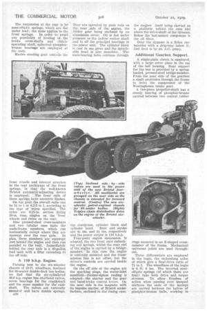
Turning now, to the six-wheeler chassis of 19-ft. wheelbase, destined for 60-seater double-deck bus bodies, we find that the six-cylindered 48.6 h.p. engine has overhead valves,• seven bearings for the crankshaft and the same number for the cant shaft. The valves are vertically mounted and have. double springs. n26 • They are operated by push rods on the near ,side. of , the engine, the rOcker gear being enclosed by an aluminium cover. Oil is fed under pressure to the hollow rocker shaft and to all the principal bearings in „ the power unit. The cylinder block is cast in one, piece and the detachable head is also monobloc. The main-bearing .bolts Continue through the, crankcase, cylinder block and cylinder head. Bore and stroke are 41 ins. and 51 ins.. respectively 'and the power output is 110 b.h.p.
Ftnir-point engine suspension Is adopted, the two front ones embodying coil springs, whilst the rear end of the engine is carried by a bridge.. member: In this case the engine is Centrally monnted and the transmission line is not offset, but the driver's controls are carried beside the engine.
On the off side of the engine are the sparking plugs, the water-inlet manifold—thermo-siphon cooling is adopted—the starter and the gear and hand-brake control levers. On the near side is the magneto with its impulse starter, of Bristol manufacture, enclosed in the timing case, the magnet itself being carried on a platform . behind the case 'and above the drive-shaft of the dynaraO. Below the last-named component is the oil filter.
Over the d3-name is a .SoIex carburetter with a drip-tray below it ; fuel feed is by an A.C. pump.
Additional Gearbox Support.
A, single-plate clutch is employed, with a large cover plate in the ton of the bell housing. Rear support for the box is provided by a springloaded, pressed-steel bridge-member. From the near side of the gearbox a shaft protrudes through the frame to drive the compressor of the Westinghouse brake gear.
A two-piece propeller-shaft has a steady bearing of phos-phor-bronze carried between two conical rubber rings mounted in an X-shaped crossmember of the frame. Mechanical universal joints are used throughout.
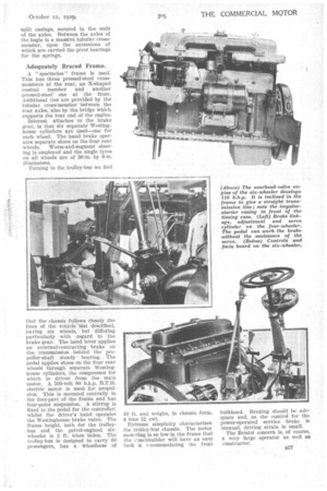
Three differentials are employed in the bogie, the underslung axles of which give a final-drive ratio of 71 to 1. The wheelbase of the bogie is -4 ft. 6 Ins. The inverted semielliptic springs (of which there are four) take both drive and torque stresses. To allow freedom cif action when passing over unequal surfaces the ends of the springs are carried between the halves of phosphor-bronze balls, working in
split casings, secured to the ends of the axles. Between the axles of the bogie is a massive tubular crossmember, upon the extensions of which are carried the pivot bearings for the springs.
Adequately Braced Frame.
A " spectacles " frame is used. This has three pressed-steel. crossmembers at the rear, an X-shaped central Member and another pressed-steerone at the front. Additional ties are provided by the tubular cross-member between the rear axles,-also by the bridge Which supports the rear, end Of the engine.
Interest attaches to the brake gear, in thatSix separateWestinghouse cylinders are used—one for each wheel.. The hand brake operates separate shoes on the four rear wheels. Worm-and-segment steering is employed and the single tyres on all wheels are of 36-in, by 8-in. dimensions.
Turning to the trolley-bus we find
that the chassis follows Closely the lines. Of the vehicle 'last 'deScribed, having six wheels, but 'differing particularly with regard to the brake gear.. The hand lever applies an external-contracting brake on the tranSmission behind the propeller-shaft steady bearing. The pedal ,apPlies shoes on the four rear wheel § through separate Westinghouse cylinders, the compressor for which is driven from the main motor. A 500-volt -80 b.h.p. B.T.H. electric motor is used for propulsion. This is mounted centrally in the fore-part of the frame and has four-point suspension. A Stirrup. is fixed to the pedal for the controller, whilst the driver's hand operates the Westinghouse brake valve. The frame height, both for the trolleybus and the petrol-engined sixwheeler is 2 ft. when laden. The trolley-bus -is designed to 'carry 60 passengers, has a wheelbase of 19 ft. arid weighs, in chassis form, 4 tons 12 cwt.
Extreme simplicity characterizes Ike trolley-bus chassis. The motor muting is so low in the frame that the ,:-•)achbuilder will have an easy task n ccommodating the front
bulkhead. Braking 'should be adequate and, as the control for the power-operated service brake is manual, driving strain is small.'
The Bristol concern is, of course, a very large operator as well. as constructor,