 1
1 2
2 3
3 4
4 5
5 6
6 7
7 8
8 9
9 10
10 11
11 12
12 13
13 14
14 15
15 16
16 17
17 18
18 19
19 20
20 21
21 22
22 23
23 24
24 25
25 26
26 27
27 28
28 29
29 30
30 31
31 32
32 33
33 34
34 35
35 36
36 37
37 38
38 39
39 40
40 41
41 42
42 43
43 44
44 45
45 46
46 47
47 48
48 49
49 50
50 51
51 52
52 53
53 54
54 55
55 56
56 57
57 58
58 59
59 60
60 61
61 62
62 63
63 64
64 65
65 66
66 67
67 68
68 69
69 70
70 71
71 72
72 73
73 74
74 75
75 76
76 77
77 78
78 79
79 80
80 81
81 82
82 83
83 84
84 85
85 86
86 87
87 88
88 89
89 90
90 91
91 92
92 93
93 94
94 95
95 96
96 97
97 98
98 99
99 100
100 101
101 102
102 103
103 104
104 105
105 106
106 107
107 108
108 109
109 110
110 111
111 112
112 113
113 114
114 115
115 116
116 117
117 118
118 119
119 120
120 121
121 122
122 123
123 124
124 125
125 126
126 127
127 128
128 129
129 130
130 131
131 132
132 133
133 134
134 135
135 136
136 137
137 138
138 139
139 140
140 141
141 142
142 143
143 144
144 145
145 146
146 147
147 148
148 149
149 150
150 151
151 152
152 153
153 154
154 155
155 156
156 157
157 158
158 159
159 160
160 161
161 162
162 163
163 164
164 165
165 166
166 167
167 168
168 169
169 170
170 171
171 172
172 173
173 174
174 175
175 176
176 177
177 178
178 179
179 180
180 181
181 182
182 183
183 184
184 185
185 186
186 187
187 188
188 189
189 190
190 191
191 192
192 193
193 194
194 195
195 196
196 197
197 198
198 199
199 200
200 201
201 202
202 203
203 204
204 205
205 206
206 207
207 208
208 209
209 210
210 211
211 212
212 213
213 214
214 215
215 216
216 217
217 218
218 219
219 220
220 221
221 222
222 223
223 224
224 225
225 226
226 227
227 228
228 229
229 230
230 231
231 232
232 233
233 234
234 235
235 236
236 237
237 238
238 239
239 240
240 241
241 242
242 243
243 244
244 245
245 246
246 247
247 248
248 249
249 250
250 251
251 252
252 253
253 254
254 255
255 256
256 257
257 258
258 259
259 260
260 261
261 262
262 263
263 264
264 265
265 266
266 267
267 268
268 269
269 270
270 271
271 272
272 273
273 274
274 275
275 276
276 277
277 278
278 279
279 280
280 281
281 282
282 283
283 284
284 285
285 286
286 287
287 288
288 289
289 290
290 291
291 292
292 293
293 294
294 295
295 296
296 297
297 298
298 299
299 300
300 301
301 302
302 303
303 304
304 305
305 306
306 AN AUTOMATIC VARIABLE GEAR.
Page 198
If you've noticed an error in this article please click here to report it so we can fix it.
A Resume of Recently Published Patent Specifications.
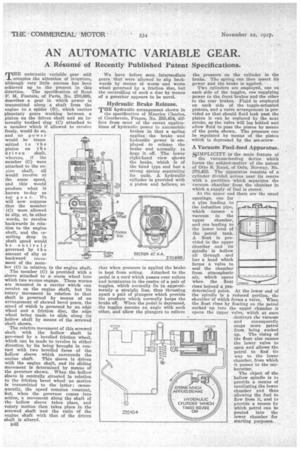
T"automatic variable gear still occupies the attention of inventors, although very little success has been achieved up to the present in this direction. The specification of Rene • F. M. Fontain, of Paris, No. 270,699, describes a gear in which power is transmitted along a shaft from the engine to a spider (B), which -carries planetary gears working between a pinion on the driven shaft and an internally toothed ring (C) attached to a member which if allowed to revolve freely, would do so, and no power would be transmitted to the pinion on the driven shaft, whereas, if the member (0) were attached to the engine shaft, all would revolve at the same speed, and this would produce what is known to-day as top gear. We will now suppose that the member (C) were allowed to slip, or, in other words, to revolve backwards in relation to the engine shaft, and the esuiting drop in shaft speed would be entirely governed by the amount of slip or backward inovement of the mem
ber (C) in relation to the engine shaft.
The member (C) is provided with a sleeve attached to a worm wheel into which two worms engage. These worms are mounted in a carrier which can revolve on the engine shaft, but its rotary movement in relation to that shaft is governed by means of an arrangement of skewed bevel gears, the speed of which is governed by an edge wheel and a friction disc, the edge wheel being made to slide along its hollow shaft by means of tim screwed shaft shown.
The relative movement of this screwed shaft with the hollow shaft is gay-rned by a bevelled friction wheel, which can be made to revolve in either direction by its being brought in contact with two bevelled faces of the hollow sleeve which surrounds the engine shaft. This sleeve is driven with the engine shaft, and its sliding movement is determined by means of the governor shown. When the hollow sleeve is centrally situated in relation to the friction bevel wheel no motion is transmitted to the latter consequently, the speed remains constant, but, when the governor comes into action, a movement along the shaft of the hollow sleeve takes place, and rotary motion then takes place in the screwed shaft and the ratio of the engine shaft with that of the driven shat is altered.
E42 We have before seen intermediate gears that were allowed to slip backwards by means of worm and worm wheel governed by a friction disc, but the controlling of such a disc by means of a governor appears to be novel.
Hydraulic Brake Release. Trm hydraulic arrangement shown in the specification of Maurice Charles,
of Courbevoie, France, No. 255,454, dif fers from most of the reeent applica tions of hydraulic power to automobile brakes in that a spring aPPlies the brake and hydraulic power is employed to release the brake and normally to keep it off. The lower right-hand view shows the brake, which is of the band type and has a strong spring separating its ends. A hydraulic cylinder is provided with a piston and bellows, so that when pressure is applied the brake is kept from acting. Attached to the Pedal is a cord which passes over rollers and terminates in the centre of a pair of toggles, which normally lie in approximately a straight line, thus thrusting apart a pair of plungers which provide the praAure which normally keeps the brake off. When the pedal is depressed, the toggles assume an angle with each other, and allow the plungers to relieve the pressure on the cylinder in the brake. The spring can then assert its power and the brake is applied.
Two cylinders are employed, one on each side of the toggles, one supplying power to the front brakes and the other to the rear brakes. Fluid is employed on each side of the toggle-actuated pistons, and a valve arrangement is provided so that should fluid leak past the piston it can be replaced by the next stroke, as the valve will lag behind and allow fluid to pass the piston by means of the ports shown. The pressure can be regulated by means of the piston which is depressed by the set-screw
A Vacuum Fuel-feed Apparatus.
SIMPLICITY ig the main feature of the vacuum-feeding device which forms the subject-matter of the patent of Otto S. Ruud, of Oslo, Norway, No. 278,452. The apparatus consists of a cylinder divided across near its centre with a partition which separates the vacuum chamber from the chamber in which a supply of fuel is stored.
At the upper end there are the usual openings, one for a pipe leading to the induction pipe, which causes a vacuum in the upper chamber, and one leading to the lower level of the petrol tank. A float is provided in the upper chamber and its spindle is all throughlhrousgh d has a head which forms a valve to seal the chamber from atmospheric air, which opens when the float rises beyond a predetermined point. At the lower end of the spindle is a reduced portion, the shoulder of which forms a valve. When the float rises by floating on the petrol sucked up into the upper chamber it opens the upper valve, which at once destroys the vacuum and consequently stops more petrol from being sucked up. The rising of the float also causes the lower valve to open and allows the petrol to find its way to the lower chamber, from which it passes to the carburetter.
The object of the hollow spindle is to provide a means of ventilating.the lower chamber and thus allowing the fuel to flow from it, and to provide a means by which petrol can be poured into the lower chamber for starting purposes.