 1
1 2
2 3
3 4
4 5
5 6
6 7
7 8
8 9
9 10
10 11
11 12
12 13
13 14
14 15
15 16
16 17
17 18
18 19
19 20
20 21
21 22
22 23
23 24
24 25
25 26
26 27
27 28
28 29
29 30
30 31
31 32
32 33
33 34
34 35
35 36
36 37
37 38
38 39
39 40
40 41
41 42
42 43
43 44
44 45
45 46
46 47
47 48
48 49
49 50
50 51
51 52
52 53
53 54
54 55
55 56
56 57
57 58
58 59
59 60
60 61
61 62
62 63
63 64
64 65
65 66
66 67
67 68
68 69
69 70
70 71
71 72
72 73
73 74
74 75
75 76
76 77
77 78
78 79
79 80
80 81
81 82
82 83
83 84
84 85
85 86
86 87
87 88
88 89
89 90
90 91
91 92
92 93
93 94
94 95
95 96
96 97
97 98
98 99
99 100
100 101
101 102
102 103
103 104
104 105
105 106
106 107
107 108
108 109
109 110
110 111
111 112
112 113
113 114
114 115
115 116
116 117
117 118
118 119
119 120
120 121
121 122
122 123
123 124
124 125
125 126
126 127
127 128
128 129
129 130
130 131
131 132
132 133
133 134
134 135
135 136
136 137
137 138
138 139
139 140
140 141
141 142
142 143
143 144
144 145
145 146
146 147
147 148
148 149
149 150
150 151
151 152
152 153
153 154
154 155
155 156
156 157
157 158
158 159
159 160
160 161
161 162
162 163
163 164
164 165
165 166
166 167
167 168
168 169
169 170
170 171
171 172
172 173
173 174
174 175
175 176
176 177
177 178
178 179
179 180
180 181
181 182
182 183
183 184
184 185
185 186
186 187
187 188
188 189
189 190
190 191
191 192
192 193
193 194
194 195
195 196
196 197
197 198
198 199
199 200
200 201
201 202
202 203
203 204
204 205
205 206
206 207
207 208
208 209
209 210
210 211
211 212
212 213
213 214
214 215
215 216
216 217
217 218
218 219
219 220
220 221
221 222
222 223
223 224
224 225
225 226
226 227
227 228
228 229
229 230
230 231
231 232
232 233
233 234
234 235
235 236
236 237
237 238
238 239
239 240
240 241
241 242
242 243
243 244
244 245
245 246
246 247
247 248
248 249
249 250
250 251
251 252
252 253
253 254
254 255
255 256
256 257
257 258
258 259
259 260
260 261
261 262
262 263
263 264
264 265
265 266
266 267
267 268
268 269
269 270
270 271
271 272
272 273
273 274
274 275
275 276
276 277
277 278
278 279
279 280
280 281
281 282
282 283
283 284
284 285
285 286
286 287
287 288
288 289
289 290
290 291
291 292
292 293
293 294
294 295
295 296
296 297
297 298
298 299
299 300
300 301
301 302
302 303
303 304
304 305
305 306
306 Maudslay.
Page 154
If you've noticed an error in this article please click here to report it so we can fix it.
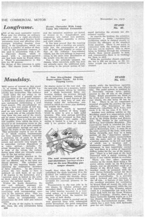
11g.E centre of interest on this stand _ is, of course, the new 45-100 h.p.
s-cylindered schassis, which is a re
[trkably fine production. The radiator itself takes the eye owing to its indsomme lines and a general appear ice suggestive of power and strength; is fitted with radiator shutters and a oyce motometer surmounting a neat inged mascot. The six-cylindered en
ne has a bore and stroke of 110 rum.
id 130 mm. respectively, and is de gned on very novel lines with a cam taft at each side of the cylinder block, iven from the rear end of the cranktaft by gears. Constructed in one unit ith the engine there is a four-forwardteed gearbox, from which the drive is niveyed to an mulerslung worm on the ack axle by means of an open propeller salt; semi-elliptic springs are used to apport the frame at the front and rear.
This particular engine is one of the mw in which' correct fundamentals ave been obtained without requiting a enormous lot of parts to be dismantled when the cylinders are decaronized, and accounts very largely for he somewhat curious disposition of re valve springs. Actually, the prings themselves are located at the op ends of the valves, the rockers easing upon what are virtually extenions of the top spring seats.
Particular! Interest attaches to the tanner in which the water cannerions are effected, and to the inlet and xhaust systems. The cylinders are overed by two separate heads, each ontaining the combustion chambers
or three cylinders. In the junction etweeu the two heads a face is reclined on each head, at an angle f 45 degrees to the horizontal, and a /Junction piece is bolted to the eylinler block which fits into the V formed metween the cylinder heads.
Within the heads themselves, the ulet and exhaust passages are trranged longitudinally at each side, he apertures of the inner ends comnunicating with corresponding apes.nres in the junction piece. Only one Ape is used—the exhaust pipe, which :bus makes an exceptionally neat irraugement for both inlet and exhaust
;Weals.
The off side of the engine is remarkably clean, the only excrescence being ISO the starter motor at the rear end. On the near side there are a magneto, water pump and dynamo driven in tandem, and a single horizontal Solex carburetter feeding the mixture through cast-in induction passages warmed by. the exhaust gases. A good feature is the provision of a deep tray of cast aluminium under the carburetter, connected to which is a drain pipe discharging outside the chassis.
A single-plate clutch is operated through the medium of three toggle levers in order to give a light pedal pressure. The nine springs providing the pressure are arranged so that they can be inserted very easily. Each spring is loaded in e cage to a point
only in. greater than its working length, thus when the back plate is assembled, the studs retaining it to the flywheel are sufficiently long to allow the nuts to engage the threads, thereby compressing the springs without the necessity for external pressure to be applied.
Transmission to the rear axle is in two stages, by tubular primary and secondary shaft. There is a self-aligning roller bearing mounted in a truncated sphere on a pressed-steel crossmember which forms the location for the ends of both shafts.
The braking system is ,carried out on very generous lines with substantial joints throughout, the pedal controlling internal-expauding brakes on all four wheels, while the hand-lever operates independent brakes in the rear wheels only. The pedal system is assisted by a Dewandre vacuum servo motor, secured to the off side of the chassis frame. Single pneumatids are fitted to the front and twin pneumatics to the rear wheels, the size being 38 ins. by 7 ins. There is an air compressor mounted alongside the gearbox for tyre inflation. ..The dimensions of this chassis are : wheelbase, 16 ft. 8 ins., and track, 5 ft. 9 ins. rear, 6 ft. front.
Another very striking exhibit on the Maudslay stand is a super-saloon coach on an hI.L.4-type chassis, with bodywork by the Duple Bodies and Motors, Ltd. The chassis is the well-known 30-70 hp. four-cylinder Maudslay. The super-saloon coach is intended for Continental touring de luxe, and has been sold to Motorways, Ltd.; it seats 16 in the main portion of the body, with seats facing forwards, and four in a back portion of the "observation saloon" type. This back portion communicates with the main part of the . body by a central gangway, to the left and right of which are a lavatory and a kitchenette respectively. The interior equipment is very beautifully carried out, ano) there is a series of ingenious folding tables for the use of the passengers. There is a bell push at the back connected with a signal warning the driver if any vehicle wishes to overtake.
There are two other • passenger vehicles on the stand, these being a 32seater saloon coach on an M.L.3-type chassis, and an all-weather coach on a chassis of the bL1a4 type. The allweather coach is arranged with the seats facing forwards, except for thesal over the wheel arches, which are arranged longitudinally. It is provided with a forward and rear entrance on the off side. A feature nf this body is the excellent provision for ventilation by hinged flaps all round, the rails and windows being permanent, while the top is demountable. The 32-seater saloon coach is a workmanlike job with a forward dash built for the Great Western Railway Company. Finally, there is a heavy hydraulic tipping wagon on a 7-8 ton chassis, fitted with the Maudslay 30-70 hp. four-cylindered engine. This . vehicle has a steel body with hydraulic gear for end tipping.