 1
1 2
2 3
3 4
4 5
5 6
6 7
7 8
8 9
9 10
10 11
11 12
12 13
13 14
14 15
15 16
16 17
17 18
18 19
19 20
20 21
21 22
22 23
23 24
24 25
25 26
26 27
27 28
28 29
29 30
30 31
31 32
32 33
33 34
34 35
35 36
36 37
37 38
38 39
39 40
40 41
41 42
42 43
43 44
44 45
45 46
46 47
47 48
48 49
49 50
50 51
51 52
52 53
53 54
54 55
55 56
56 57
57 58
58 59
59 60
60 61
61 62
62 63
63 64
64 65
65 66
66 67
67 68
68 69
69 70
70 71
71 72
72 73
73 74
74 75
75 76
76 77
77 78
78 79
79 80
80 81
81 82
82 83
83 84
84 85
85 86
86 87
87 88
88 89
89 90
90 91
91 92
92 93
93 94
94 95
95 96
96 97
97 98
98 99
99 100
100 101
101 102
102 103
103 104
104 105
105 106
106 107
107 108
108 109
109 110
110 111
111 112
112 113
113 114
114 115
115 116
116 117
117 118
118 119
119 120
120 121
121 122
122 123
123 124
124 125
125 126
126 127
127 128
128 129
129 130
130 131
131 132
132 133
133 134
134 135
135 136
136 137
137 138
138 139
139 140
140 141
141 142
142 143
143 144
144 145
145 146
146 147
147 148
148 149
149 150
150 151
151 152
152 153
153 154
154 155
155 156
156 157
157 158
158 159
159 160
160 161
161 162
162 163
163 164
164 165
165 166
166 167
167 168
168 169
169 170
170 171
171 172
172 173
173 174
174 175
175 176
176 177
177 178
178 179
179 180
180 181
181 182
182 183
183 184
184 185
185 186
186 187
187 188
188 189
189 190
190 191
191 192
192 193
193 194
194 195
195 196
196 197
197 198
198 199
199 200
200 201
201 202
202 203
203 204
204 205
205 206
206 207
207 208
208 209
209 210
210 211
211 212
212 213
213 214
214 215
215 216
216 217
217 218
218 219
219 220
220 221
221 222
222 223
223 224
224 225
225 226
226 227
227 228
228 229
229 230
230 231
231 232
232 233
233 234
234 235
235 236
236 237
237 238
238 239
239 240
240 241
241 242
242 243
243 244
244 245
245 246
246 247
247 248
248 249
249 250
250 251
251 252
252 253
253 254
254 255
255 256
256 257
257 258
258 259
259 260
260 261
261 262
262 263
263 264
264 265
265 266
266 267
267 268
268 269
269 270
270 271
271 272
272 273
273 274
274 275
275 276
276 277
277 278
278 279
279 280
280 281
281 282
282 283
283 284
284 285
285 286
286 287
287 288
288 289
289 290
290 291
291 292
292 293
293 294
294 295
295 296
296 297
297 298
298 299
299 300
300 301
301 302
302 303
303 304
304 305
305 306
306 F.W.D.
Page 145
If you've noticed an error in this article please click here to report it so we can fix it.
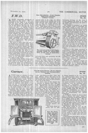
. AMOST remarkable six-wheeler is staged on this stand. The construction of the bogie is so arranged that the drive can be taken through the four wheels at the rear—or at the wilt of the driver—through the front
wheels as well. A special inverted Semi-elliptic suspension system enables each pair of wheels on the bogie to rock angularly at a remarkable angle, thus excessively uneven ground can be negotiated without fear of straining, anypart of the transmission or springs. Forward of the gearbox the new vehiele 1' closely resembles the F.W.Ds model which was built some Months ago fer the War Department. The gearbox, however, is different.
The drive is taken from the rear ot the gearbox by a propeller 'shaft, equiptied with metal universal joints, which passes to a special casing extending from the forward axle of the bogie. This easing contains a silent-chain reduction gear, and provides the drive to Inc bevel pinion on this axle. The propeller shaft is continued rearwards by another cardan shaft which conveys the drive to a second easing of similar construction. There. is no differential between the two axles of the bogie.
A feature of the driving arrangement Is the length of shaft between the axles. With axles 4 ft. apart, the centres of the universal joints are usually approximately 2 ft. pitch, but the bevel drive is so arranged that the pinions are at
opposed sides of the axles; one pinion being in front of the leading axle of the bogie and the other behind that at the rear, so that the length between the universal joints is increased to 4 ft. 7 ins. This means that a smaller angle for a given wheel movement is obtained, thereby greatly reducing the wear in the
universal joints and increasing the efficiency all round.
Tubular torque rods with ball joints connect the bogie axles to a channel cross-member fitted between the castings which carry the spring fulcrums. The braking on the rear wheels, in addition to being compensated, affords an increasing leverage as the lever ii moved, enabling the slack to be take, up quickly and increasing the power a the same time.
One chassis is mounted ' on trestle; and arranged with a cross-shaft pro vided with cranks to raise and towel the axles and so tilt-the wheels in orde: to demonstrate the movement of tb. rear axles and the freedom of the frann and springs from twisting stresses.
Also exhibited is a standard 5-tor chassis with the driver behind tilt engine. This particular chassis is fittee with an auxiliary gearbox, giving u choice of six speeds forward and two re verse. The speed on the highest gear b. stated to be about 24 m.p.h. In ordei to shovr: alternative tyre equipment, tip wheels on one side of the chassis arc shod with solid tyres, and on the othei side with pneumatics of 36-in. by 8-in
section.
Visitors to this stand interested is cross-country transport should make a point of examining the half-track maebine, with Roadless tracks at the back and 36-in. by 8-in, pneumatics on thc front wheels, which, incidentally, arc arranged to drive. The equipment oi this vehicle includes a power-drives winch with 500 ft. of cable.
Another new component staged for the first time at Olympia on this concern's stand is a double-reduction wheel of the type used for the Royal National Lifeboat tractor.