 1
1 2
2 3
3 4
4 5
5 6
6 7
7 8
8 9
9 10
10 11
11 12
12 13
13 14
14 15
15 16
16 17
17 18
18 19
19 20
20 21
21 22
22 23
23 24
24 25
25 26
26 27
27 28
28 29
29 30
30 31
31 32
32 33
33 34
34 35
35 36
36 37
37 38
38 39
39 40
40 41
41 42
42 43
43 44
44 45
45 46
46 47
47 48
48 49
49 50
50 51
51 52
52 53
53 54
54 55
55 56
56 57
57 58
58 59
59 60
60 61
61 62
62 63
63 64
64 65
65 66
66 67
67 68
68 69
69 70
70 71
71 72
72 73
73 74
74 75
75 76
76 77
77 78
78 79
79 80
80 81
81 82
82 83
83 84
84 85
85 86
86 87
87 88
88 89
89 90
90 91
91 92
92 93
93 94
94 95
95 96
96 97
97 98
98 99
99 100
100 101
101 102
102 103
103 104
104 105
105 106
106 107
107 108
108 109
109 110
110 111
111 112
112 113
113 114
114 115
115 116
116 117
117 118
118 119
119 120
120 121
121 122
122 123
123 124
124 125
125 126
126 127
127 128
128 129
129 130
130 131
131 132
132 133
133 134
134 135
135 136
136 137
137 138
138 139
139 140
140 141
141 142
142 143
143 144
144 145
145 146
146 147
147 148
148 149
149 150
150 151
151 152
152 153
153 154
154 155
155 156
156 157
157 158
158 159
159 160
160 161
161 162
162 163
163 164
164 165
165 166
166 167
167 168
168 169
169 170
170 171
171 172
172 173
173 174
174 175
175 176
176 177
177 178
178 179
179 180
180 181
181 182
182 183
183 184
184 185
185 186
186 187
187 188
188 189
189 190
190 191
191 192
192 193
193 194
194 195
195 196
196 197
197 198
198 199
199 200
200 201
201 202
202 203
203 204
204 205
205 206
206 207
207 208
208 209
209 210
210 211
211 212
212 213
213 214
214 215
215 216
216 217
217 218
218 219
219 220
220 221
221 222
222 223
223 224
224 225
225 226
226 227
227 228
228 229
229 230
230 231
231 232
232 233
233 234
234 235
235 236
236 237
237 238
238 239
239 240
240 241
241 242
242 243
243 244
244 245
245 246
246 247
247 248
248 249
249 250
250 251
251 252
252 253
253 254
254 255
255 256
256 257
257 258
258 259
259 260
260 261
261 262
262 263
263 264
264 265
265 266
266 267
267 268
268 269
269 270
270 271
271 272
272 273
273 274
274 275
275 276
276 277
277 278
278 279
279 280
280 281
281 282
282 283
283 284
284 285
285 286
286 287
287 288
288 289
289 290
290 291
291 292
292 293
293 294
294 295
295 296
296 297
297 298
298 299
299 300
300 301
301 302
302 303
303 304
304 305
305 306
306 AN INTERESTING NEW SIX-CYLINDER CHASSIS.
Page 121
Page 122
If you've noticed an error in this article please click here to report it so we can fix it.
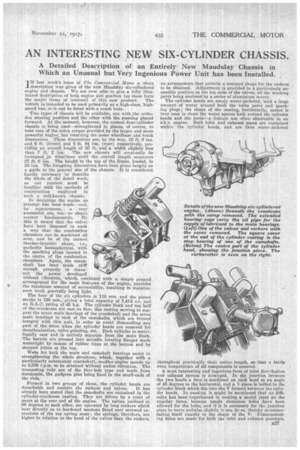
A Detailed Description of an Entirely New Maudslay Chassis in Which an Unusual but Very Ingenious Power Unit has been Installed.
TN last week's issue of The Commercial Motor a short 1. description was given of the new Maudslay six-cylindered engine and chassis. We are now able.to.give a fully
trated description of both engine and gearbox (as these form the major items of interest) of this new product. The vehicle is intended to be used primarily as a high-class, highspeed bus, or it can be fitted with a coach body.
Two types of chassis will be available, one with the orthodox steering position and the other with the steering placed forward. At the moment, however, the normal four-cylinder chassis is being used—strengthened in places, of course, to take care of the extra torque provided by the larger and more powerful engine, hut retaining the same wheelbase and track dimensions. These dimensions are, by the way, 16 ft. 8 ins.
and ,6 ft. (front) and 5 ft. e ins. (rear) respectively, pr siding an overall length of 26 ft. and a width slightly less
thau 7 ft. 2 ins. The new chassis will eventually be increased in wheelbase until the overall length measures 27 ft. 6 ins. The height to the top of the frame, loaded, is 25 ins. The foregoing dimensions have been given largely as a guide to the general size of the chassis. It is considered hardly necessary to describe the whole of the detail work, as our readers must be familiar with the methods of construction employed ita such a well-known. chassis.
In designing the engine all attempt has been made—and, by appearances, a very successful one, too—to obtain correct fundamentals. By this is meant that the valves have been disposed in such a way that the combustion chambers can be machined all over, and be of the correct thermo-dynamic shape, i.e., perfectly hemispherical, with the sparking plugs located in the centre of the combustion chambers. Again, the crankshaft has been made stiff enough properly to transmit the power developed without vibration, which, combined with a simple general arrangement for the main features of the engine, provides the maximum amount of accessibility, resulting in maintenance work generally being light.
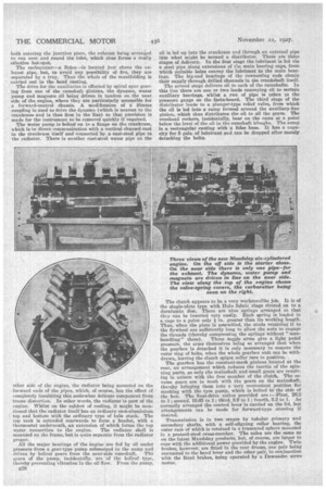
The bore of the six cylinders is 110 mm. and the piston stroke is 130 mm., giving a total capacity of 7,412 c.c. and an R.A.C. rating of 45 h.p. The cylinder block and top half of the crankcase are cast en bloc, this casting serving to support the seven main ,bearings of the crankshaft and the seven main bearings to each of the camshafts, which are formed integral with this unit, in order to avoid dismantling any part of the drive when the cylinder heads are removed for decarbonization, valve grinding, etc. Each cylinder is centrifugally cast and is entirely separate from the main block. 'The barrels are pressed into suitable locating flanges made watertight by means of rubber rings at the bottom and by stepped joints at the top,
Webs for both the main and camshaft beatings assist in strengthening the whole structure, which, together with a particularly substantial crankshaft, enables engine speeds up to 3,500 r.p.m. to be attained without undue vibration. The connecting rods are of the four-bolt type and made from duralumin, the gudgeon pins being fixed in the small-ends of the rods.
Formed in two groups of three, the cylinder heads are detachable and contain the rockers and valves. It has already been stated that the camshafts are contained in the cylinder-crankcase casting. They are driven by a train of gears at the rear end of the engine. The valves, inclined at
90 degrees to each other, are operated by long rockers which bear directly on to hardened washers fitted over screwed extensions of the top spring seats; the springs, therefore, are higher in relation to the head of the valves than the rockers,
an arrangement that permit's a compact shape for the rockers to be obtained. Adjustment is provided in a particularly accessible position at the top ends of the valves, all the working parts being enclosed by a series of aluminium covers.
The cylinder heads are amply water-jacketed, with a large amount of water around both the valve ports and sparking plugs ; the shape of the casting, incidentally, makes it very easy to clean the water spaces both around the cylinder heads and the ports—a feature not often obtainable in an o.h.v. engine. Both inlet and exhaust pipes are contained within the cylinder heads, and are thus water-jacketed throughout practically their entire length, so that a fairly even temperature of all components is ensured.
A most interesting and ingenious form of inlet distribution and exhaust system is arranged. In the junction between the two heads a face is machined on each head at an angle of 45 degrees to the horizontal, aud a V-piece is bolted to the cylinder block which fits into the V formed between the cylinder heads. In passing, it might be mentioned that no difficulty has been experienced in making a sound joint on the angular faces, because ample clearance holes have been allowed for the bolts, and if it is necessary for the junction piece to Move endwise slightly it can do so, thereby accommodating itself exactly to the shape of the V. Communicating holes are made for both the inlet and exhaust passages,
both entering the junction piece, the exhaust being arranged to run over and round the inlet, which dine forms a really effective hot-spot.
The carburetter—a Solex—is located just above the exhaust pipe, but, to avoid any posoibility of fire, they are separated by a tray. Thus the whole of the manifolding is carried out in the head casting.
The drive for the auxiliaries is effected by spiral spur gearing from one of the camshaft Pinions, the dynamo, water pump and magneto all being driven in tandem on the near rdde of the engine, where they are particularly accessible for a forward-control chassis. A. modification of a Simms coupling is used to drive the dynamo (which is nearest to the crankcase and is thus fbrst in the line) so that provision is made for the instrument to be removed quickly if required.
The water Pump is bolted on to a flange on the crankcase, which is in direct communication with a vertical channel cast in the crankcase itself and connected by a cast-steel pipe to the radiator. There is another cast-steel water pipe on the
other side of the engine, the radiator being mounted on the forward ends of the pipes, which, of course, has the effect of completely insulating this somewhat delicate component from frame distortion. In other words, the radiator is part of the engine. Whilst on the subject of cooling, it might be mentioned that the radiator itself has an ordinary east-aluminium • top and bottom with the ordinary type of tube stack. The top tank is extended rearwards to form a header, with a thermostat underneath, an extension of which forms the top
water connection to the engine. The radiator shell is mounted on the frame, but is quite separate from the radiator. proper.
All the major hearings of the engine are fed by oil under pressure 'from a gear-type pump submerged in the sump and driven by helical gears from the near-side camshaft. -The gears of the pump. incidentally, are of the helical type, thereby preventing vibration in the oil flow. From the pump,
E28 oil is led up into the crankcase and through an external pipe into what might be termed a distributor. There are three stages of delivery. In the first stage the lubricant is led via a steel pipe along extensions of the main bearing caps, from which suitable holes convey the lubricant to the main bearings. The big-end bearings of the connecting rods obtain their supply through drilled channels in the crankshaft itself.
The second stage delivers oil to each of the camshafts, In this line there are one or two leads conveying oil to certain auxiliary bearings, whilst a run of pipe is taken to the pressure gauge on the facia-board. The third stage of the distributor leads to a plus ger-type relief valve, from which the oil is led into a sump formed around the auxiliary-lrine pinion, which thus distributes the oil to all the gears. The overhead rockers, incidentally, bear on the cams at a point below the level of the oil in the camshaft trhughs. The sump is a rectangular casting with a false base. It has a capacity for 5 gals. of lubricant and can be dropped after merely detaching the bolts.
The clutch appears to be a very workmanlike job. It is of the single-plate type with Halo fabric rings riveted on to a duralumin disc. There are nine springs arranged so that they can he inserted very easily. Each spring is loaded in a cage to a point only 1 in. greater than its working length. Thus, when the plate is assembled, the studs retaining it to the flywheel are sufficiently long to allow the nuts to engage the threads (thereby compressing the springs without "man
handling" them). Three toggle arms give a light pedal pressure, the arms themselves being so arranged that when the gearbox is detached it is only necessary to remove the outer ring of bolts, when the whole gearbox unit can be withdrawn, leaving the clutch spigot roller race in position. _
The gearbox has the constant-mesh pinions located at the rear, an arrangement which reduces the inertia of the spinning parts, as only the mainshaft and small gears are revolving in unison with the free member of the clutch. The reverse gears are in mesh with the gears on the mainshaft, thereby bringing them into a very convenient position for meshing with the tyre pu3np, which is bolted to the side of the box. The final-drive ratios provided are :—First, 26.2 to 1; second, 15.65 to 1; third, 8.9 to 1; fourth, 52 to 1. As normally arranged the control /ever is carried on the lid, but arrangements can be made for forward-type steering if desired.
Transmission is in two stages by tubular primary and secondary shafts, with a self-aligning roller bearing, the outer rage of which is retained in a truncated sphere mounted in a pressed-steel cross-member. The axles are the same as on the latest Maudslay products, but, a course, are larger to cope with the additional power provided by the engine. Twin brakes, however, are fitted in the rear drums, one pair being connected to the hand lever and the other pair, in conjunction with the front brakes, being operated by a Dewandre servo motor.