


A Boring Attachment for Fitting te Tractors
Page 26
If you've noticed an error in this article please click here to report it so we can fix it.
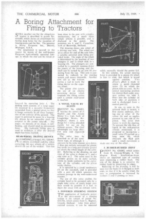
STILL 'another use for the ubiquitous tractor is described in patent No. 614,605, which shows an attachment for boring deep holes for the reception of fencing posts and the like. The patentee is Harry Ferguson Inc., Detroit; Michigan, U.S.A.
The attachment is secured to the tractor by means of the well-known Ferguson hydraulically operated .linkage,in which the rear can he raised or lowered by operating to:Tr L The drilling units consists of a large auger (2) mounted in a movable. framework' suspended from a gimbal: Pivot,:...so,that• it hangs vertically at all times irrespective of the contour of-the. ground. auger is powered by gears in a housing (3), driven. by ;an': extensible shaft (41. coupled to the power take-off,' aneer, on ceount of its -shape, :is self
. feeding, and should need no doWnward
force, Tile hydranlic-liffin:e gear is used to withdraw it after the desired: depth has been:reache'il.
REAR-IVHEEL TILTING DEVICE , .
ACCO RI) 1 tO7patetrieNid: 626,967, . lel obtain itability 'when cornering,: tfi' rear..Vvheels..of a vehicle should tilt out of die vertical. This has been done in the past with comple).-. mechanisms, but a much more simple scheme is possible, and is disclosed in the patent. The patentees are I. and C. Cornelisk, both of Beverwijk, Holland. The' drawing shows one wheel of a driving rear axle. The wheel can pivot about the end of the axle tube, a suitable universal joint being pravided inside. The angle of the wheel is determined by the position of two plungers (1 and 2) ..which slide in a houSing (3). The plungers are controlled by is camshaft running down the :centre. of the housing, and the shaft can be turned by an arm (4) projecting front the top. This arm is connected by rochvOrk to the steering system and moves therewith. Another arm 45) at the bottom L'arries a rod to work the tilting device on the opposite wheel.
The patent also covers the use of an electric governing device which suspends the tilting action until a certain road-speed is reached.
A NOVEL VALVE BY , AUSTIN
PAT.ENT No. 620,0E3, bearing the names of .1.•• Harefeli: and. The Austin Motor C Lid., both of Longbridge Works, Birmingham, shows a new design. for a valve, intended, mainly for use on the exhaust system. • The Chief advantages are large elTec: tive. area and improved.
CO0iirq.
The valve may be described as Of the semi sleeve type, as although it , operates in the same manner as a sleeve,. it cities not entirely surround the piston. but oacs in a long part-circular groM:e cut down the wholelength of the cylinder. Referring to' the' drawing, an end view of the valve is rhown at 1, and .a side view at. 2 . The valVe seats in the cylinder groove on its outer surface, whilst its inside conforms to the curvature of the cylinder, and the piSton wOrki therein. • •••
It is operated by. a. crank."mechanisro (3) on the camshaft, 'and is provided with a port (4) which uncovers the exhaust' passage in the well-understood Manner.'
The use of this valve enables the cylinder head to be occupied only by a single inlet valve, of much. larger area than would be possible if it had to share the space with an exhaust valve.
A POWERED STEERING SYSTEM
THE .application of hydraulic power to the servo-motor of a steering system is the subject of patent No. 615,726, which comes from L. Baghuis, Utrecht, Holland. :Like most powerassisted systems, it can be operated
safely manually should the poWee fail. In this scheme, the actual :steering force is provided by a piston (1) which is free to slide, but which is keyed against rOtation. T h e driver's effort is made to rotate a quick threaded screw (2) on which the piston runs as a nut. In the 'central non:actingposition (as shown) fluid under pressure arrives via 'inlet 3, flows into the cylinder on both sides of partition 4 and is discharged from a central port (5).
In use, as soon as the screwed shaft is turned, it first moves endwayS, closing one or other Of the valves (6) and so applies pressure to one side of the piston. The latter then move, to work the steering.
-prevent the'idle flow of • liquid -in: the mid-position already ,mentioned, it .iS proposed to: incorporate a -small valve (7) carried on a long stem (8), which obstructs the fluid path until a small movement is madeone way or the other:
RUBBER-BUSHED .10INT
PATENT No. 620,882, which comes from H. Clayton-Wright, ".4, Tiddington Road, Stratford-on-Avon, shOws an improved type of'.steerirng joint employing a rubber bush. The aim of the design is to conserve the ritb.ber bush by preserving its edges.
Referring to the drawing, it will be Seen that the bush (1) is flanged at both ends, so that if it he axially tilted, the area in compression is increased by washers 2 and -3 coming to bear.