


A NEW USE FOR THE INDUSTRIAL TRUCK.
Page 30
If you've noticed an error in this article please click here to report it so we can fix it.
A Resume of Recently Published Specifications.
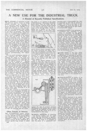
THE SPHERE of operations of the industrial electric truck is being rapidly extended. An invention of T. C. Dawkins, which is described in patent specification No. 216,979, is do. yiseel with that end in view, and provides for its employment when sweeping the platforms of railway stations or the floors of factories. The device 'which is the subject of this patent consists of a rotary brush, carried on a. trailer which is adapted to be coupled to the rear end of one of the usual types of industrial truck. The brush is arranged to be driven by the wheels of the trailer, the driving medium consisting of a pair of chains and a pair of gearwheels, both being of such climensioes that the speed of the brush is increased in comparison with that of the
wheels which drive it. Provision is made for lifting and lowering the brush and its driving mechanism, whilst a suitable radius rod keeps the centre distances of the chain sprockets constant notwithstanding this adjustment.
The two most interesting features of this invention are the method of coupling the trailer to the truck and the means provided far collecting the dust and disposing ,of it when the col lector is full or nearly so. Dealing first with the method of attachment, the side-members of the frame of the brush are carried forward, so that they will embrace the rear end of the truck. Two holes, one in each side-member, are arranged to come into line with corresponding holes in the side frames of the tractor or truck, and the connection is made by inserting a pin in each pair of holes, The rear end of the trailer is supported on a castor wheel.
To allow the combined vehicle to be mancenvred round corners, it is recommended that the brush attachment be used in conjunction with that type of truck which embodies an elevating gear for the platform. By its use the front end of the brush attachment, the wheels and brush will be lifted clear of the floor, being left supported upon the castor wheel only, allowing it to be steered quite easily.
The dust container is trapezoidal in elevation and rectangular in plan, as may be seen on reference to one of the accompanying illuetrations. It is quite enclosed but for two openings, one at each aide of the brush, round which the lower floor of the container is carried in the form of an arch. For the purpose of disposing of the collected dust the container is tipped round its extremity, suitable screw gear being provided for the purpose. The rear wall is designed as a flap, to open and allow egress for the refuse, whilst an inner flap prevents any of it falling out through the openings near the brush.
Other Patents of Interest.
AN INTERESTING engine lubrica
tion system is described in specification No. 217,147, by the Vulcan Motor and Engineering Co. (1906), Ltd. It. embodies a pump of the gear type, which is driven off the camshaft by a vertical spindle long enough to enable B48 the pump to be located in the sump of the crankcase. The pump, therefore, draws direct from the sump, and delivers, through a special groove formed in the body of the pump, into the interior of its driving shaft, which is hollow for a portion of its length Where the hollow in this shaft ends means of egress for the oil is provided and it travels thence, through a chamber which surrounds the shaft, into a large and conveniently accessible fitter of the usual. cylindrical type in which the oil is delivered from the pump into the interior of a gauze cylinder, through the walls of which it must pass on its way to the bearings and other parts which require it.
One of the special features of this system is that the need for external oil piping is obviated. After leaving the filter the oil passes into a chamber at the end of the camshaft, which is hollow. It travels thence along the interior of the camshaft and makes its way to the main engine bearings through passages drilled through the camshaft and its bearings, and through the webs of the crankcase. Even the ball elease . valve, which provides against the risk of excessive pressure developing in the system, has an outlet formed in the material of the crankcase, enabling the excess oil to be returned direct to the sump.
VARIOUS METHODS of mounting the Dunlop cushion tyre on roadwheel rims are described in specification No. 216.988, by the Dunlop Rubber Co., Ltd. In some it is arranged to take the place of a pneumatic tyre mounted upon a demountable rim, and is supported on that rim by means of wedges. In others a new type of rim is employed on which the base of the tyre itself, supplemented by split bands, is automatically wedged.
COMPENSATION of the springing in
accordance with variations in the loading is provided in the design patented in specification No. 217,001, by making the upper surface of the ends of the top leaves of the springs cam shaped. As the load increases, and the spring flattens under it, these camshaped ends bring the points of contact between the springs and the underside of the frame, against which they rub, closer together, thus shortening the dicetive length of the springs and providing the compensation desired. The patentee is C. G. Nevatt, and the springing will be remembered as being used successfully on the Bristol chassis.
BRAKE GEAR of the type which
. operates brakes WI all four wheels simultaneously is described in specification No. 217,005, by E. Fairbrother and C. S. Windsor. The pedal is used for the operation, and it controls the frontwheel brakes through a cable and the rear brakes through either cables or rods. There is a compensating gear on the pedal shaft to equalize the effort of the two sets of brakes, and it is so designed that, in the event of one set of brake gear failing, the other set would still operate, when the compensating link, or other means, had reached the limit of its movement. Provision is made, through a one-way clutch, for the rear brakes alone to be operated by a side lever.
SUPERCHARGING an engine, so ar
to compensate for the drop in atmospheric pressure which occurs as high altitudes are attained, is a problem which has been occupying the attention of aeronautical engineers for some time. One more solution of it is offered by G. Formica, and is described by him in Rpecifi cation Mn. 217,138. He is in this invention concerned with the control of the supercharging apparatus, and his object is so to arrange the control that the de,gree of supercharging is automatically varied in accordance with the pressme of the atmosphere wherein the engine works. The medium employed is an enginedriven compressor, and the control is by a valve, which opens or closes e series of ports. The valve is operated by a dashpot contrivance, which depends directly upon the atmospheric pressure for its working, and is arranged so that, when at sea-level, the ports are open, and the compressor merely blows air through them, but when, as the result of climbing, the pressure of the atmo'sphere drops, then the ports commence to close, and some part of the compressed air is directed into the cylinders, the amount varying with the degree of closing of the ports, which, again, is governed by the dashpot operating in accordance with the diminishing or increasing effect of the pressure of the atmosphere.