


Patents Completed.
Page 22
If you've noticed an error in this article please click here to report it so we can fix it.
A Piston-valve Engine. Rolls-Royce Priming Device. A New Frontwheel Drive. Challiner Built-up Wheels.
Copies of complete specifications of the patents published on this page can be obtained from ,The Sales Brcrich, Patent Office, Holborn, W.C., at the cost of sixpence for each specification:
C. W. H. CRALLINER and L. BROWN, No. 11,194, dated 6th May, 1914.—The accompanying drawings show a new construction of wheel according to whioh each of the spokes is
made in two parts divided longitudinally. The complete spoke may be of circular, roctangular or cruciform cross-sec
tion and the outer ends are bent over to form the rim of the wheel. The two parts of the spoke are welded together throughout their length and the abutting ends forming the rim are also welded together. The inner ends of the spokes are of tapered box-shape, the two parts being welded together along the adjoining edges. Lateral displacement of the inner ends is prevented, apart from the welded joints, by a key locked in grooves in the abutting faces of two box sections. These grooves may be radial or transverse, or both. Various modifications are described and illustrated in the specification.
E. W. HIVES AND ROLLS-ROYCE, LTD., No. 2840, dated 22nd February, 1915.--In this priming device an auxiliary chamber is provided beneath the float-feed chamber in the carburetter, and it is connected on one side to the induction pipe of the engine and at the other side to a hand-operated pump. This auxiliary chamber is filled with fuel, and when it is required to start the engine, the pump is operated to drive this fuel mixed with air into the induction pipe. A conk is provided between the auxiliary chamber and the induction pipe to cut off the connection when the engine is running normally, and this cock is preferably connected to a three-way cock which forms the connection for the pump to the auxiliary chamber. The three-way cock is used in order to render this pump available for supplying the ordinary pressure feed tank. The fuel is supplied to the auxiliary chamber preferably through a. non-return valve in the bottom of the float-feed chamber.
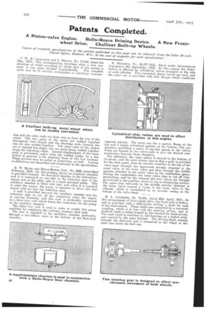
E. MICHJELS, No. 20,377./1913, dated under International Convention 9th September, 1912 —In this engine the distribution is effected by cylindrical valves arranged at the side of each cylinder. Two concentric piston valves are used, and the outer one is provided with four flanges which constitute
separate pistons. The inner one has a narrow flange at the top and a larger cylindrical portion at the bottom this construction providing a series of annular spaces in the valves. Ports are formed in the valve-walls to give the desired communication between these chambers.
For admission, the inner piston is moved to the bottom of its stroke, and the outer piston rises so that a path is provided for the inlet gases, from an annular chamber at the top of the valve-chest through the uppermost annular chamber in the outer valve, to the inner valve and then through the middle annular chamber in the outer valve to the combustion space. During the compression the inner valve rises to cut off communication, and for the exhaust the two valves are brought downwards to the position shown in the accompanying section. The gases pass outwards by the middle annular chamber in the outer valve around a recess in the inner valve to the exhaust, which is constituted by an annular casing at the bottom of the valve-chest.
H. A. ANDERSEN, No 10,521, dated 28th April, 1914.—In this arrangement of front-wheel drive the front axle is hollow, and is provided with a differential driving a shaft for each of the road-wheels. These shafts are connected by a universal coupling, which is in line with the steering pivots, and is situated inside a casing formed by the bracket for these pivots. The road wheel is mounted by ballhearings on a hollow stub. axle carried by the same bracket. The driving-shaft extends through the stub-axle and is connected to the wheel at the outer end inside the hub cap.