


AN INTERESTING PLANETARY GEARBOX.
Page 49
Page 50
If you've noticed an error in this article please click here to report it so we can fix it.
A New Design Notable for the Small Number of Gearwheels Employed.
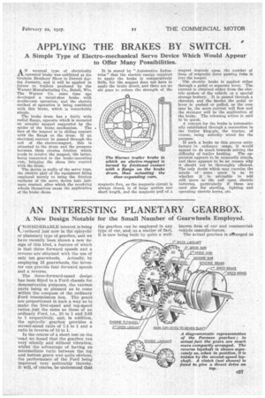
CONSIDERABLE interest is being evinced just now in th& epicyclic or planetary type of gearbox, and we have recently been shown a new design of this kind, a feature of which is that three forward speeds and a reverse ate 'obtained with the use of only ten gearwheels. Actually, by employing 13 gearwheels, the inventor can provide four forward speeds and a reverse.
The three-forward-speed design has been fitted to a Ford chassis for demonstration purposes, the varimis parts being so planned as to come within the compass of the ordinary Ford transmission box. The gears are proportioned in such a way as to make the first-speed and top-speed ratios just the same as those of an ordinary Ford, i.e., 10 to 1 and 3.63 to 1 respectively, and, in addition, the epicyclic gearbox provides a second-speed ratio of 7.4 to 1 and a ratio in reverse of 14 to 1.
In the course of a short test on the 'road we found that the gearbox ran very silently and without vibration, whilst the advantage of having an intermediate ratio between the top and bottom gears was quite obvious, the performance of the Ford being improved very noticeably thereby. It will, of course, be understood that
the gearbox can be employed in any type of car, and as a matter of fact, it is now being built by quite a well The actual gearbox is aPtanged so comkactly that a drawing of the part g would hardly be sufficiently clear, so that we reproduce a diagrammatic view, in which the gears have been purposely spaced out in order to show the principle involved more closely ; the numbers of teeth employed for each wheel are indicated by the figures on the drawing.
In the centre of the flywheel there Is a spigot bearing which supports the forward end of the driven shaft, and adjacent to this bearing the main sun-wheel is keyed to the shaft. This sun-wheel can, of course, rotate independently of the flywheel. The flywheel carries three equally spaced layshafts, on each of which is mounted a pair of planet gears, so made that each pair must rotate as one.
The forward gear of each pair meshes with the main sun-wheel, whilst for each of the rearmost layshaft gears an independent sunwheel is provided, carrying a sleeve on which a brake drum is mounted ; there are thus three telescopically arranged sleeves connecting the sunwheels to three brake drums mounted side by side. In addition to these parts there are two which are not shown on the drawing, these being a disc riding freely on the
driven shaft, which serves to support the rear ends of the layshafts, and a clutch whereby the driven shaft can be coupled direct to the flywheel for top speed.
When the rearmost brake drum is held stationary by means of shoes, first speed is obtained in the following way :—The. gripping of the drum has the effect of holding the firstspeed sun-wheel stationary, so that, as the flywheel rotates (driven by the engine), the rearmost gear on the first-speed layshaft rolls round the fixed sun-wheel and thus imparts a spinning movement to the other gear on the same layshaft. This other gear is, therefore, not only carried round by the flywheel, but is also forced to turn on its own axis ; the main sun-wheel, with which it is in engagement, is, therefore, carried round at a speed considerably less than that of the flywheel. In actual fact, the numbers of teeth used is such that the driven shaft turns at about one-third engine speed. It will be understood that while this is occurring the other gears and the brake drums turn idly.
• Second speed is obtained in exactly the same way, but, owing to the difference in the sizes of the gears, the driven shaft is speeded up, revolving at approximately half engine speed. The engagement of the reverse brake holds stationary the rearmost sunwheel, which is of large size, and it will be noticed that the corresponding layshaft .arries gears the foremost one of which is larger than the other.
Consequently, the layshaft gear which is rolling round the fixed sunwheel is smaller than the corresponding gear which is in mesh with the main sun-wheel. As a result, the main sun-wheel is forced to turn in a direction the reverse of that in which the flywheel is rotating.
A new form of control has also been patented by the inventor, which will be fitted to another demonstration car now in course of construction. This embodies self-centring contracting brake shoes, so applied to the drums as to ensure an equalized action, with a foolproof control embodying a single spring. The particular brake which this spring operates is selected by cams controlled by the change-speed lever.
The development of this interesting gearbox and of the operating gear is the concern of a newlyformed company, known as Furness Gears, Ltd., whose address is 169, Coldharbour Lane, London, S.E.5.