


SENTINEL WAGON DESIGN.
Page 30
If you've noticed an error in this article please click here to report it so we can fix it.
A Résumé of Recently Published Patents.
Specification No. 156341, by S. E. Alley, would appear to indicate impending changes in the design of the Sentinel steam wagon, although, as a matter of fact, it does not necessarily follow that this is the case.
The,Sentincl, as most of our readers are aware, is at present driven by a single roller chain, which transmits the drive from a sprocket pinion on the end ot the crankshaft to a, wheel bolted to the differential case which is on die
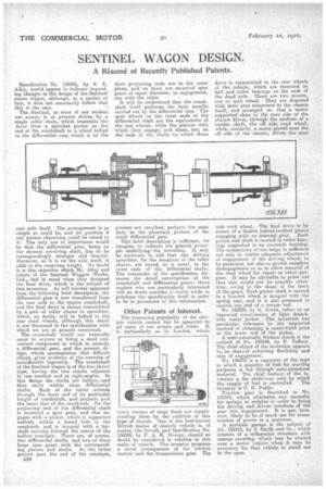
rear axle itself. The arrangement is as 'simple as could be, and we question if any serious objections could be raised to it. The only one of importance would be that the differential gear, being on the slowest revolving shaft, has to be correspondingly stronger and heavier. Moreover, as it is on the axle itself, it adds to the unsprung weight. No doubt it is this objection which Mr. Alley and others of the Sentinel Waggon Works, Ltd., had in mind when they designed the final drive, which is, the subject of this invention. As will become apparent from the following brief description, the differential gear is now transferred from the rear axle to the engine crankshaft, and the final drive is thence transmitted by a pair of roller chains to sprockets, which, no doubt, will be bolted to the rear road wheels, although this detail is not discussed in the specification with which we are at present concerned.
The crankshaft would not naturally occur to anyone as being a most convenient component in which to embody a differential gear, andthe present design, which accomplishes that difficult object, gives evidence of the•exercise,of considerable ingenuity. The crankshaft i of the Sentinel wagon s of the two-throw type, having the two cranks adjacent to one another and at right-angles. In this •lesign the shafts are hollow,-.and they carry within them differential shafts. Each of the latter extends through the inner end of its !particular length of crankshaft, and projects past the Inner face of the crank web. On the projecting end of the differential shaft is mourited a spur gear, and this engages with a pinion, which is supported entirely within a bored hole in the crank-web, and is integral with a layshaft running through the centre of the hollow Crankpin. There are, of course, two differential shafts, and two of these large spur gears with the corresponding pinions and shafts. As the latter project past the end of the crankpin,
B26 their projecting ends are in the same plane, and on them are mounted spur gears of equal diameter, in engagement, one with *the other.
It will be understood that the crankshaft itself performs the duty usually carried out by the differential case. The spur wheels on the inner ends of the differential shaft are the equivalents of the sun wheels, while the pinions with which they engage, and those, too, on the ends of the shafts to which those
pinions are attached, perform the same duty as the planetary pinions of the usual differential gear.
This brief description is sufficient, we imagine, to indicate the general principle underlying' the invention. It May be necessary to add that the driving sprockets, for the reception of the roller chains, are keyed, as is usual, to the outer ends of the differential shafts, The remainder of the specification discusses the detail construction of the crankshaft and differential gears; those' readers who are particularly interested will no doubt consider it worth while to purchase the 'specification itself in order to be in possession of this information.
Other Patents of Interest.
The increasing popularity of the electric vehicle cannot but be apparent to all users of our streets and roads. It is particularly so in London, where
many owners of large fleets are supple. menting them by the addition of this type of chassis. One of the best-known British makes of electric vehicle is' of course, the Orwell. and Specification No. 156398, by P. A. H. Mossay, should no doubt be considered in relation to this make of vehicle. 'The inventor proposes a novel arrangement of the electric motors and the transmission gear. The
drive is transmitted to the rear wheels of the vehicle, which are mounted on ball and roller bearings on the ends of the dead axle. There are two motors, one to each wheel. They are disposed with their axes transverse to the chassis itself, and arranged so that a motor supported close to the near side of the chassis drives, through the meditim of a cardan shaft, the off side .road wheel, while, similarly, a motor placed near the off side of the chassis,' drives the near side road wheel. The final drive is by means of a double helical-toothed pinion engaging with an internal gear. Each pinion and shaft is carried in roller bearings supported in an eccentric bushing. The eccentricity of the latter is sufficient ' not only to enable adequate adjustment of engagement of the driving wheels to be perfected, but also to permit complete disengagement so as to allow removal of the road wheel for repair or other purpose. It may be advisable to point out that this would not be possible otherwise, owing to the shape of the teeth of the gears. Each pinion shaft is carried in a bracket which is integral with the spring seat, and it is also prepared to receive one end of a torque rod.
No. 156320, by G. Green, refers to an improved construction of light detachable water jacket. Theinvention has particular reference to the improved method of obtaining a water-tight joint at the lower end of the jacket.
A semi-automatic friction clutch is the subject of No. 153549, by P. Tuff cry. The chief object of the invention appears to be thats of achieving flexibility and ease of engagement. No. 156272 is a vaporizer of the type in which a quantity of fuel for starting purposes is fed through semi-absorbent material. The chief feature of the invention is the multi-way cock by which the supply of fuel is controlled. The inventor is C. G. Puffin.
Friction gear is described in No. 135501, which eliminates any necessity for springs or weights in order to bring the driving and, driven members 01 the gear into engagement. It is not, however, likely to be of much use for transmission of power in a motorcar. A portable garage is the subject of No. 156413, by J. Smith and Co., which consists of a collapsable structure with canvas covering,' which may be erected over a motor vehicle when it may be necessary for that vehicle to stand out in the open. ,