


• OVERHAULING THE GUY.
Page 22
Page 23
Page 24
Page 25
If you've noticed an error in this article please click here to report it so we can fix it.
No. 10.—The Guy 2-2-Aton Chassis. How to Take Advantage of the Maker's Foresight in Design—Features which Differ from Usual Practice and Facilitate Repair Work-Where Users and Repair Men Score—Saving 'Time and Obviating Wear.
APRELIMINARY inspection of the Guy 2-24 ton chassis, prior to undertaking repairs of any kind, or embarking on a complete overhaul, will reveal.the fact that the manufacturers have displayed welcome, and almost unusual, foresight in the general design and arrangement of their chassis, from the repair shop point of view.
Many tames, in these columns, we have appealed to manufacturers in general, to. allow themselves to be influenced by that view-point, when producing a new design, more than has been customary in the past; it is therefore a pleasure to be able to record an instance in which repair shop foresight has been exercised to quite a remerkable extent.
We haw& heard this vehicle described as an " ownerdriver's " lorry—a term that is used more frequently in comuy3tion with light touring cars—but which, in so far as it connotes the reduction of lubrication points to a minimum, the simplification of mechanism, and its convenient arrangement so that both assembly and disa.ssembly operations throughout the chassis are facilitated, is perfectly applicable to the ton Guy. .
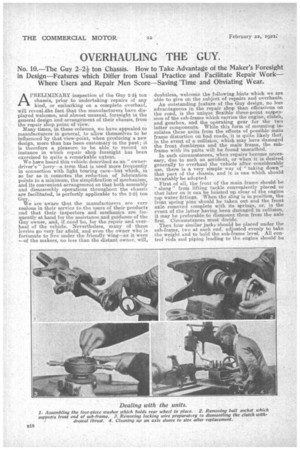
We are aware that the manufacturers are very zealous in their service to the users of their products and that their inspectors and mechanics are frequently at hand for the assistance and guidance of the Guy owner, and, if need be, for the repair and overhaul of the vehicle. Nevertheless, many of these lerries go very far afield, and even the owner who is fortunate to live under the friendly wing—as it were —of the makers, no less than the distant owner, will, doubtless, welcome the following hints which we are able to give on the subject of repairs and overhauls. An outstanding feature of the Guy design, no less advantageous in the repair shop than efficacious on the road, is the unique flexible three-point suspension of the sub-frame which carries the engine clutch, and, gearbox, and the operating gear for ate two latter components. While this form of mounting insulates these units from the effects of possible main frame distortion on bad roads, it is quite likely that, in the event of a collision, which may have damaged the front dumbirens and the main frame the subframe with its pnits will be found unscathed. In such circumstances, when repairs become necessary, due to such an accident, or when it is desired generally to overhaul the vehicle after considerable use, there is a very simple way of ".taking down" that part of the chassis, and it is one which should invariably be adopted.
First of all, the front of the main frame should be " slung " from lifting tackle conveniently placedthat later on it can be hoisted up clear of the engne tap water fittings. When the sling is in position, the . front spring pins should be taken out and. the front axle removed complete with its springs, or, in the event of. the latter having been damaged in collision, it may be preferable to dismount them from the axle first. Circumstances must decide.
Then four similar jacks should be placed under the . sub-frame, two -at each end, adjusted. evenly to take the weight and to hold the sub-frame level. All control rods and piping leading to the engine should be uneoupIed, and (if this has not already been done) the engine and radiator should be drained of water and the latter taken off. The bolts should also he taken out of the flange which holds the exhaust pipe to its manifold. The next thing to do is to unship the forward end of the propeller shaft_ This is a matter of loosening the clips on the leather gaiter, and taking out the nine bolts in the flange of the large circular cover. This can then be slipped back along the shaft, exposing the ring universal. joint. Split the ring by taking out the eight belts which hold the halves together, and the shaft can then be cast free. The brake rods also must be uncoupled. Then undo the °otter bolt which holds the dog on the end of the starting handle, and slip the latter out. The sub-frame, now supported by the four jacks, is attached to the main frame by one large ball joint at the front, by 'smaller ball joints to eaeh of the brackets which hang from a cross tube at the rear.
To deal with the front joint, first remove the wire ring which locks the big circular nut at the back of the curving front portion of the aub-franae..This type of locking ring is used in eeveralplaces on the chassis, and comes off easily when tackled with the tang of a file or a screwdriver. Then unscrew the circular nut. Now tackle the front portion of the ball housing, which is held in. position in the main frame front cross-member by four nuts. Remove these, and the half housing. The ball can now her pulled out in front, and the forward end of the sub-frame is free.
At the rear, both bell joints are provided with circular serrated housing nuts,locked by a " tongue " held under the brass lubricator which supplies each joint. Remove this, and unscrew the nuts. Each ball has a tapered shank, by which it is held in the bracket, and there is aunt at the end. Take off these nuts, and then the ball pins can. be driven out. This frees the rear end of the sub-frame. It is new possible to hoist up the front end of the main frame (the rear wheels forming a fulcrum), and to run it back, leaving the sub-frame with its unite complete .on the-four jacks. It would be difficult to conceive a better arrangement, from the point of view of convenience and accessibility. It is now easy to examine, and, if necessary, to dismantle, the engine., clutch, and gearbox.
Sub-frame Anchorage.
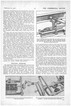
The patented sloping detachable head arrangement of the Guy engine will be appreeiated velum it is desired to examine this unit. When the detachable heads and the offside crankcase doors have been removed, the connecting rod bolts ,ean easily be undone, and the pistons complete with their rods removed through the top of the cylinders. If the cylinder heads stick they can be forced off by utilizing two special setscrews (provided in the kit) in the tapped holes, provided in each head. The valves also will be found then to be very accessible for grinding in, if they require it. It is unlikely that the rocker arm bearings will be found to require any attention, as they are of such robust dimensions, Valve tappet adjustment can he carried out when the long aluminium valve cover on the near side has been taken off. If it is desired to take out the camshaft for any reason, the rockers must be held back off the came, while the shaft is withdrawn from the front of the engine together with it driving wheel, as it can be.
.Although it will be -seen that the oil pump is housed in the lower half of the crankcase, where it is driven. bya vertical shaft from the camshaft, there need be no apprehension in dropping the base chamber in order to get at the main bearings or to clean the filter gauges, as the shaft drives through the medium of a tongued joint, which simply slips apart. The MI pump can be removed as a whole by undoing two nuts.
In the. event of main hearing wear, or a scored crankshaft, the latter can be reground, by the Makers if desired, and the bearings taken up in the usual way. Should a badly-worn or scored cylinder bore make it necessary to regrind the cylinders, they should be opened out to either 5, 10, or 15-1,000 in. oversize, as the makers can , supply replacement
pistons to these dimensions. They will regrind cylinders if required. It is important that the oil filter on the crankcase should be removed and cleaned several times a week.
The oil pipes for the forced lubrication system are cast in the sides and webs of the crankcase. The passages are of large diameter and it is very unlikely that they will ever become choked, and obstruct the flow of oil, unless some foreign matter finds its way intoethe systenr through carelessness in reassembling an engine. (In theiordinary way the oil passes through no fewer than four filters.) In the unlikely event of obstruction, however, there are two ways of clearing the ducts. One is by screwing down the oil release valve, situated just above the front engine cover, so that the pressure is increased throughout the circuit, or, the plugs at each end of the main pipe can be taken out, the main bearings removed, and the duets probed and cleaned mechanically. Leakage from the water pump spindle is provided against by a. spring-loaded washer made of special material. Should leakage by any chance occur, the washer can be renewed by removing the pump—a matter of taking out the two bolts in the oval delivery pipe flange, and of slacking off the clip which holds the pump body to the crankcase.
Do Not Remove the Disc Joint Bolts.
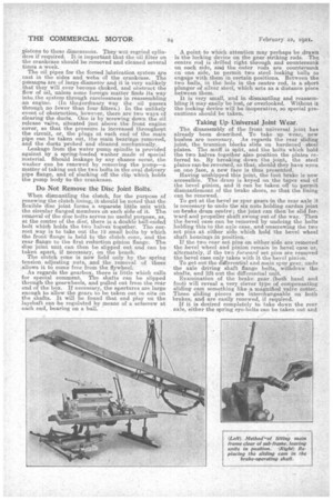
When dismantling the clutch, for the purpose of renewing the dutch lining, it should be noted that the flexible disc joint forms a separate little unit with the circular flanged members on each side of it. The removal of the disc bolts serves no useful purpose, as, at the centre of the dim', there is a double ball-ended bolt which holds the two halves; together. The correct way is to take out the 12 small bolts, by which the front' flange is held to the clutch cone, and the rear flange to the first reduction pinion flange. The disc 'joint unit can then be slipped out and can be taken, apart, if necessary, on the bench. The clutch cone is now hold only by the spring tension adjusting nuts, and the removal of these .allows it to come free from the flywheel.
As regards the gearbox, there is little which calls for special comment. The, shafts can be slipped through the gearwheels, and pulled out from the rear end of the box. If necessary, the apertures are large enough to allow the gears to be taken out a situ on the shafts. It will be found that end play on the layshaft can be regulated by means of a setscrew at each end, bearing on a ball. A point to which attention may perhaps be drawn is the locking device on the gear striking rods. The centre rod is drilled right through and countersunk on each side, and the outer rods are countersunk en one side, to permit two steel locking balls to engage with them in certain positions. Between the two balls, in the hole in the centre rod, is a short plunger of.silver steel, which acts as a distance piece between them.
It is very small, and in dismantling and reassembling it may easily be lost, or overlooked. Without it the locking device will be inoperative, so special precautions should be taken.
Taking UpUniversal Joint Wear.
The disassembly of the front universal joint has already been described. To take up wear, new bushes are necessary. As regards the rear sliding joint, the trunnion blocks slide on hardened steel plates. The muff is split, and the bolts which hold the two halves together also position the plates referred to. By breaking down the joint, the steel plates can-be reversed, so that, should they have wpm on one face, a new face is thus presented. Having unshipped this joint, the foot brake is now accessible. The drum is keyed on the taper end of the bevel pinion, and it can be taken off to permit dismantlement of the brake shoes, so that the lining can be renewed.
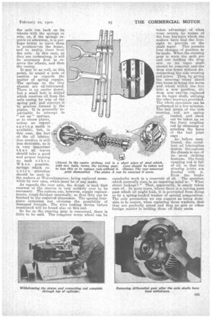
To get at the bevel or spur gears in the rear axle it is necessary to undo the six nuts holding cardan joint on brake drum centre; the joint can then be slid forward and propeller shaft swung out of the way. Then the bevel ease can be removed by undoing the bolts holding this to the axle ease, and unscrewing the two set pins at either side which hold the bevel wheel shaft housings in position..
If the two rear .set pins on either side are removed the bevel wheel and pinion remain in bevel case or, alternately, if the two forward set pins are removed the bevel case only takes with it the bevel pinion.
To get out the differential and main spur gear, undo the axle driving shaft flange bolts, withdraw the shafts, and lift out the differential unit.
Examination of the brake gear (both hand and foot) will reveal a very clever type of compensating sliding earn something like a magnified valve cotter. These sliding pieces are interchangeable on both brakes, and are easily renewed, if required.
If it is desired completely to take down the rear axle, either the spring eye-bolts can he taken out and
the axle run back on itswheels with the springs in situ, or, if the springs require no attention, it is perhaps better to leave them in positionnon the frame, and to unship them from the axle. In this case, as they are underslung, it will be necessary first to remove the wheels, and then
• the casing.
It may be as well, at this point, to sound a note of caution as regards the matter of spring repairs. The springs on the Guy chassis are oil-lubricated. There is no centre dowel, but a small hole is drilled which receives oil from the axle easing by way of the spring pad, and conveys it to grooves formed in the plates. It is generally inadvisable to attempt to " set up " springs, or to renew plates, unless an expert , spring sraith is available, lout, in this ease, the fact of the oil lubrication renders it still less desirable, as it is very important that all leaves should take a good and proper beaming on each other. When possible, springs which require attention should be sent to the makers at Wolverhampton, being replaced meanwhile by new ones, which must be of any make. As regards the rear axle, the desigt is such that renewal of the sleeves is very unlikely ever to be necessary. The makers can, however, supply replace _ roents, rough-finished externally, so that they can be finished to the required dimension. The special fourpiece retaining nut obviates the possibility of damaged threads. The wire locking device before mentioned will be found also on this nut.
So far as the steering gear is concerned, there is little to be said. The complete warm wheel can he
taken advantage of when wear occurs, by means of the four keyways which the makers have had the foresight to provide on the shaft taper. This permits four changes of position to be made. When the steering gear is worn the split pin and nut holding the drop arm on its taper shaft should be removed andithe drop arm freed without disconnecting the side steering rod joints Then, by giving the steeringe wheel about two turns to bring the .V701m and_ wheel within the box into a new position, the drop arm oanlbe replaced on its, taper shaft, utilizing the other keyways provided. The whole operation can be performed in a few minutes. The ball joints of the'side steering rod are spring loaded, and slack can be ta-ken ,up on the front coupling rod by skimming or grinding the faces
• of the ball joint caps As before mentioned, the excellent oil lubrication
stem throughout the 'ehassis is one of its most striking features. The front coupling rod is full of oil, so that the steering joints are flooded with it. Even the brake camshafts work in a reservoir of oil. The question which naturally rises in an inquiring mind is-: What about leakage?" That, apparently, is amply taken care of. In most cases, where there is a moving part past which oil might leak, it is prevented from doing so by a spring-loaded washer of special composition. The only precaution we can suggest as being desirable is to ensure, when replacing these washers, that they are perfectly sound and that no grit or other foreign matter is holding them off their seats.