


With Intent to Improve.
Page 24
If you've noticed an error in this article please click here to report it so we can fix it.
A Weekly Summary of Recent Patents, of Interest to the Maker and User of Commercial Motor Vehicles.
Selected and Abridged by H. S. Hall, A.M.I.A.E.
A Group of Sunbeam Patents.
The Patent Office records slow a certain liveliness on the part of the Sunbeam Motor Car Co., Ltd., of Moorfields Works, Wolverhampton. We observed recently that no fewer than eight consecutive patents concerning internal-cembustion-engine design had been granted to this concern.
Mainly for Aero Engines.
The application of all of these is particularly directed towards the construction of aeroplane engines and aeroplanes generally. Several of them however, are, incidentally, of considerable interest to our readers as pointing the way to probable developments of petrol engines for all purposes; others are not so likely, at an early period, to be adapted in engines for commercialvehicles, and consequently are not dealt with on this page. With the increased demand for fuel economy, the possibility that highspeed, and what are frequently termed high-efficiency engines, may shortly be embodied in the construction of commercial-motor chassis is one which may not hastily be denied. Conse9uently it behoves us to keep in touch with all such improvements as may from time to time be recorded.
In the former category of the patents to which we refer may be mentioned one apecification describing improvements in link work, and particularly applicable to the construction of connecting rods for V-type engines. Another one deals with the starting by hand, or by motor, of large engines, such as are now being used in aeroplanes; it is of special application and needs not to be dealt with on this page. Another deals with camshaft driving iy means of a train of gears, the object being the shortening as much as possible of the length of an overhead shaft.
This drawing shows the improved arrangement of overhead-valve gear ; attention is directed to the oil-hole in the camshaft, the drainage for excess lubricant, and the method of carrying the rockers in the hand-hole cover.
(.62 Overhead-valve Gear.
Two specifications of interest concern the operation of the tappets of overhead valves; their simplicity is no less apparent than their usefulness. One, No. 103,160, is a design of casing for an overhead camshaft, particularly adapted to obviate a difficulty -hitherto encountered with such ,constructions in regard to the escape of oil from the casing along
the tappets. Incidentally, the accessibility of the tappets is increased by the adoption of this improvement. Reference to one of cur illustrations will show that the difficulty has been simply overcome by providing a sump in the casing, or, in other words, by lifting the top of the tappet guide above the main level of the bottom of the casing, providing means of drainage for excess lubricant. The additional accessibility of the gearing is attained by carrying the rocking levers which intervene between 'cams and tappets on brackets, which are cast in one/ with small hand-hole covers provided on the casing,
Tappet Lubrication.
The other improvement, as recorded in patent specification No. 103.165, concerns the lubrication of the cams. This
is effected by using the hollow camshaft as an oil pipe. Holes are provided in the plane of each cam through which oil flows in a continuous stream, lubricating everything in the plane of the tappet—overhead cam, rocker, or tappet. The need for suitable drainage arrangements, as indicated in the previous specification, will be realized.
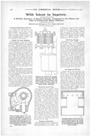
Oil Pump Design. Specification No. 103,162 concerns engine lubrication, the arrangement of oil pumps which the specification describes being designed to provide independent means of lubrication for the minor bearings of the eugine, the main system, for the principal journals, being, to all intents and purposes, unaffected. Ordinarily it has become the rule to force oil to the main bearings and rely upon the overflow or splash for the lubrication of other points, such as camshaft bearings, etc. In the arrangement suggested, a single pump is divided into two i
parts, as shown n the illustration which appears on this page; one, the lower and larger portion, delivers oil under pressure to the main bearings, the other one circulates oil to the casings which are of secondary importance in this regard. The two systems are ind:Tendent.
An Improved Piston.
Another patent concerns piston construction. It has for some time been known that A. triangular shaped groove in the outside of the piston wall so cut that it presents at its upper edge a surface at right angles to the cylinder wall, and at its lower edge a surface at an acute angle to the wall, is effective in reducing the passage of oil to the top of the piston. The improvement covered by this patent consists • of connecting such triangular shaped groove to the inside of the piston casting; this is effected by drilling a number of holes as shown in our illustration.