


Separate Suspension for Each Wheel
Page 56
Page 57
If you've noticed an error in this article please click here to report it so we can fix it.
AN unusual suspension system that appears to have certain advantages over orthodox arrangements has been devised by the Swass Suspension Co., Ltd., 15, Grey Street, Newcastle-onTyne. Credit for the development of this system is due both to its inventor, Mr. D. Brown, M.I.Mech.E., M.I.A.E., arid to Mr. F. Geo. Lundi, a local solicitor and an enthusiastic motorist who introduced the first ear to Newcastle some 35 years ago.
Preliminary details of the arrangement were given in last week's issue of The Commercial Motor.
It is understood that this system has been undergoing tests for a long time, and that those engineers who have tried it are favourably impressed. The word " Swass " stands for "separate wheel
anti-skid suspension." This explanation also serves to outline certain of the major claims for the design.
Although a superficially similar System has been developed with some success on the Continent, it is understood that the SWASS patents pre-date it and, according to expert opinion, are sound.
-B42
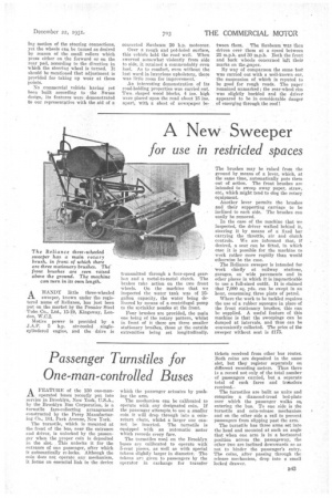
The system, in brief, comprises the provision of a separate bell-crank lever to support each wheel ; this lever is pivoted upon the chassis frame, Timken or plain bearings being employed. The horizontal portion of each lever is about four times as long as the vertical part, thereby resulting in any motion of the wheel being transferred to the flexible medium in the form of a direct corn
pression of one-quarter the amplitude.
To the end of this short, vertical lever is pivoted a horizontal rod on which is placed a number of thick rubber discs separated from each other by thin metal discs. At the one end of this series there is a metal plate attached firmly to the horizontal rod, whilst the opposite end is anchored to the chassis frame. Consequently, as the wheel rises the rubber discs are compressed.
For each rear wheel, a second or auxiliary " pile " of these discs is provided, and is so arranged that it comes into action only after the main pile has been compressed to a certain pre-deter mined extent. By this means it is claimed that a progressive action is
obtained so that the system is equally effective whatever the variation in the load carried by the vehicle.
When the front wheels of a vehicle are sprung independently of one another, a conventional steering layout is liable to produce wheel wobble and other faults. A special stabilized steering design has, therefore, been evolved.
Each front wheel is. mounted on a king pin which can slide up or down as well as rotate. In order to provide location for* the king pins there are lateral radius rods—one for each king pin and coupled to its lower end— whilst the guide takes the form of a bearing carried by each extremity of a special cross-member.
The brake anchor plate has formed on it two machined pads, or tracks, one on each side of the king pin. In contact with each of these tracks is a roller mounted on a lug which, although able to turn about the king pin, does not move vertically in relation to the chassis frame. To this mechanism the steering is connected.
Consequently, as the road wheels move up or down, there is no correspond big motion of the steering connections, yet the wheels can be turned as desired by reason of the small rollers which press either on the forward or on the rear pad, according to the direction in which the steering wheel is turned. It should be mentioned that adjustment is provided for taking up wear at the Points.
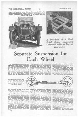
No commercial vehicle having yet been built according to the Swass design, its features were demonstrated to our representative with the aid of a converted Sunbeam 20 h.p. motorcar.
Over a rough and pot-holed surface, this vehicle held the road well. When swerved somewhat violently from side to side, it retained a commendably even keel. As to comfort, even without the last word in luxurious upholstery, there was little room for improvement
An interesting demonstration of its road-holding properties was carried out. Two., shaped wood blocks, 4 ins, high were placed upon the road about 15 ins. apart, with a sheet of news/wiper be
tween them. The Sunbeam was then driven over them at a speed between 25 m.p.h. and 30 m.p.h. Both the front and back wheels concerned left their marks on the ,paper.
By way of comparison the same test was carried out with a well-known car, the suspension of which is reputed to be good for rough roads. The paper remained unmarked ; the rear-wheel rim was slightly buckled and the driver appeared to be in considerable danger of emerging through the roof I