


A Two-speed
Page 52
If you've noticed an error in this article please click here to report it so we can fix it.
Back Axle
A Rosurne of Recently Published Patent Specifications
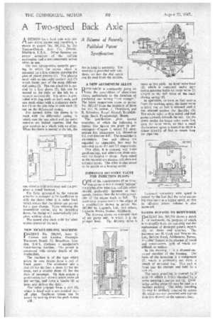
ADESIGN for a back axle with two gear ratios, normal and overdrive, is shown in patent No. 587,312, by the Timken-Detroit Axle Co., Detroit,
Michigan, U.S.A. Other features are power actuation of the shifting mechanism and a semi-automatic action when in use.
The axle incorporates epicyclic gearing in which the crown wheel is mounted on a free member carrying the pins of planet pinions (1). The planets mesh with an internally toothed ring (2) which forms part of the main differential casing (3). The sun wheel (4) is carried by a free sleeve (5); this can be moved to the right or the left by a vacuum actuator (6). The sleeve is provided with dog teeth on both ends, and can mesh either with a stationary member (7) on the axle tube or with teeth (8) cut on the differential casing.
For normal drive, the sleeve is in mesh with the differential casing, in which case the sun wheel and the outer annulus are locked together, and the gear revolves as a whole with no effect. When the sleeve is moved to the left, the sun wheel is held stationary and the gear gives a speed increase.
The force generated by the vacuum actuator is arranged to be insufficient to shift the sleeve when it is under load, which means that the driver can pre-set for a gear change. Upon relieving the transmitted torque, say by throttling down, the change will automatically take place without shock.
The patent also deals with the lubrication system of the unit.
NEW TICKET-ISSUING MACHINE
DATENT No. 586,944, from 9.
Gibson and London Passenger Transport Board, 55, Broadway, London, S.W 1, discloses a conductor's ticket-issuing machine. The patent is concerned with certain details of the mechanism.
The machine is of the type which prints its own tickets from a roll of blank paper. The conductor sets a dial (1) for the fare, a drum (2) for the stage, and a smaller drum (3) for the class of passenger. He then presses a push-button (not shown) which locks all the settings, and turns a handle (4) to
print and deliver the ticket. • The ticket emerges from a slot (5), which is fitted with a saw-toothed tearoff edge. Duplicate tickets can be issued by holding down the push-button for as long as necessary. The macnine is provided with windows, so that the dial totals can be read from the outside.
A NEW ALUMINIUM ALLOY
RESEARCH is continually going on into the possibilities of aluminium alloys, particularly in the direction of producing one having "hot strength." The latest suggestions come in patent No. 587,117 from the Secretary of State for Air, H. Sutton, I. Thompson, and E. Brimelow, Royal Aircraft Establishment, South Farnborough, Hants.
The specification gives several examples, of which the following is typical (the figures are given in percentages):—Copper 2, nickel 2.5, magnesium 0.6, manganese 1.5, chromium 0.2, and titanium 0.07. The remainder is aluminium. Iron and silicon are regarded as impurities, but may be tolerated up to 0.3 and 0.2 respectively.
This alloy, it is claimed, will make good castings, and others are given suitable for forging to shape. Parts suited to the material are pistons, cylinders and cylinder-heads. The alloy is also stated to be usable as a bearing metal.
IMPROVED DELIVERY VALVE FOR INJECTION PUMPS
r-ANE of the requirements of an injec
tion pump is that it should "unload" the piping after injection, and this action should preferably increase at high speeds, because then the breathing capa
city of the engine tends to fall. To meet these requirements is the object of a modification shown in patent No. 587,904 by Lagonda, Ltd., and others, Lagonda Works, Staines, Middlesex.
The drawing shows an enlarged view of the pump unit, in which 1 is the plunger bore. The delivery valve is made in two parts—an inner valve-head (2), which is contained under light spring pressure inside an outer valve (3) subject to the full force of the main closing spring (4).
In operation, as soon as fuel arrive from the working space, the inner valve is lifted, but no fuel is released until it has abutted against the shoulder (5). The whole valve is then raised and fuel passes upwards towards the exit. On the down stroke the larger valve seats first, then the inner valve, so that a small displacement space is formed to allow a minor quantity of fuel to return from the pipe-line.
Increased unloading with speed is caused by the fact that the valve assembly rises more at a higher speed, so that its effective return volume is also increased.
EASIER REPAIRS TO BODYWORK
DATENT No. 587,799 shows a detail
of bodywork, the purpose of which is to simplify both the assembly and the replacement of damaged panels, especially on buses and coaches. The patentees are H. Cook and Weymanns, Ltd., Station Road, Addlestone, Surrey. The chief feature is the absence of wood and wood-screws, both of which are difficult to replace.
In the drawing, I is a channel-sectioned member of the framing. The basis of the invention is a component (2), which is preferably cut from a length of extruded bar. This unit is fitted into the channel and held by a bolt (3).
The outer panelling is covered by a strip (4) which is firmly clamped by ,a screw entering a,captive nut (5). Dovetailed rubber strips (6) may be used as a resilient packing The inside panelling (7) may be similarly attached by screws (8), which are also provided with captive nuts (not shown) on the opposite face.