


MAKING BEST USE OF THE FORD.
Page 22
If you've noticed an error in this article please click here to report it so we can fix it.
Valuable Advice on Every Phase of Ford Transport, Which Will Appeal to the Owner Driver and Repairer
IN THIS series of hints concerning the Ford light chassis and ton truck wherever they are employed for commercial purposes, we endeavour .to 'deal with the subject from every view-point, so_that, the advice given will appeal to the owner, driver, maintenance engineer or mechanic.
We shall welcome for inclusion {among the hints those which have proved of valife to individual users, and will make suitable remuneration for any published. What we desire are the results of practice.
Readers are recommended to obtain the original "Book of the Ford," which constitutes a, complete manual dealing with the Ford caro. the van and the truck. 2s. ad. post free from the offices of this journal.
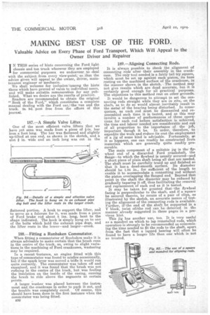
187.7—A Simple Valve Lifter.
One of the most efficient valve lifters that we have yet seen was made from a piece of bar iron a foot long. The bar was flattened and slightly up-tilted at one end, as shown in the sketch, and a i slot in. wide and an inch long was cut n the flattened portion. A hook to support the lifter, and to serve as a fulcrum for it, was made from a piece of Ford brake rod about 8 ins, long, bent to the shape indicated. The hook is simply hung on to one of the bolts which hold the exhaust pipe dogs, and the lifter rests in the lower—and larger—crook.
188,—Fitting a Runbaken Commutator.
When fitting a commutator of Runbaken make it is always advisable to make certain that the brush runs in the centre of the track, as, owing to slight variations in the machining of Ford crankcases, washering may be required.
In a recent instance, an engine fitted with this type of commutator was found to misfire occasionally, but if the spark lever was moved a trifle it would run quite correctly. The commutator was taken off and examined, and it was found that the brush was not rufining in the centre of the track, but was fouling the insulation on the inside of the casing, causing the brush to ride above the segments at certain points.
A larger washer was placed between the instrument and the crankcase m order to pack it out, and the trouble was completely cured. Of course, this should have been done in the first instance when the commutator was being fitted.
B30
189.—Aligning Connecting Rods.
It is always possible to check the alignment of connecting rods after 'their assembly in the crankcase. The only tool needed is a fairly tall try square, which must be set up against each piston, its base resting on the machined surface of the crankcase, in the manner shown in the sketch. The method may not give results which are dead accurate, but it is certainly good enough for all practical purposes. The objections to this method rest on other grounds.
It would be dangerous to attempt to set the connecting rods straight while they are in situ, on the shaft, as to do so would almost inevitably result in the metal of the bearing being disturbed. In consequence, as each rod must be dismantled and reassembled each time it is tested, and as this may involve a number of performances of these operations for each rod before satisfaction is achieved, the time and labour needed are considerable and out of all proportion to the importance of the job, important though it be. In order, therefore, to expedite the work and reduce its cost the employment of a jig of some kind is advisable. Fortunately, ro it so happens, one can readily be constructed from materials which are generally quite readily procurable.
The main component of a suitable jig is the flywheel end of a. discarded Ford crankshaft, the flange—to which the flywheel is usually secured—and a short piece of plain shaft being all that are needed. The shaft must be carefully trued up and finished so that it has a dead-smooth surface. Its diameter should be 1.24 in., for sufficient of the length to enable it to accommodate a connecting rod without the piston overlapping the flanged end. Beyond that point in the shaft the diameter may be reduced by gradually tapering it off, thus facilitating the removal and replacement of each rod as it is tested. It may be taken for granted that the flywheel facing is perpendicular to the-shaft, and if a square be secured thereto, by means of a pair of clips, as illustrated by the sketch, an accurate means of testing the alignment of the connecting rods is available. Further, if•the end of the shaft be supported in a V block, twist ofithe rod can be detected in the manner already suggested in these pages in a previous hint.
This jig has another use, too. It is very useful as a mandrel on which to lap remetalled rods, which operationis strongly to be recommended as economizing the time needed to fit the rods to the shaft, apart from the fact that a lapped bearing will often be found to have a longer life than one which is not so treated.