 1
1 2
2 3
3 4
4 5
5 6
6 7
7 8
8 9
9 10
10 11
11 12
12 13
13 14
14 15
15 16
16 17
17 18
18 19
19 20
20 21
21 22
22 23
23 24
24 25
25 26
26 27
27 28
28 29
29 30
30 31
31 32
32 33
33 34
34 35
35 36
36 37
37 38
38 39
39 40
40 41
41 42
42 43
43 44
44 45
45 46
46 47
47 48
48 49
49 50
50 51
51 52
52 53
53 54
54 55
55 56
56 57
57 58
58 59
59 60
60 61
61 62
62 63
63 64
64 65
65 66
66 67
67 68
68 69
69 70
70 71
71 72
72 73
73 74
74 75
75 76
76 77
77 78
78 79
79 80
80 81
81 82
82 83
83 84
84 85
85 86
86 87
87 88
88 89
89 90
90 91
91 92
92 93
93 94
94 95
95 96
96 97
97 98
98 99
99 100
100 101
101 102
102 103
103 104
104 105
105 106
106 107
107 108
108 109
109 110
110 111
111 112
112 113
113 114
114 115
115 116
116 117
117 118
118 119
119 120
120 121
121 122
122 123
123 124
124 125
125 126
126 127
127 128
128 129
129 130
130 131
131 132
132 133
133 134
134 135
135 136
136 137
137 138
138 139
139 140
140 141
141 142
142 143
143 144
144 145
145 146
146 147
147 148
148 149
149 150
150 151
151 152
152 153
153 154
154 155
155 156
156 157
157 158
158 159
159 160
160 161
161 162
162 163
163 164
164 165
165 166
166 167
167 168
168 169
169 170
170 171
171 172
172 173
173 174
174 175
175 176
176 177
177 178
178 179
179 180
180 181
181 182
182 183
183 184
184 185
185 186
186 187
187 188
188 189
189 190
190 191
191 192
192 193
193 194
194 195
195 196
196 197
197 198
198 199
199 200
200 201
201 202
202 203
203 204
204 205
205 206
206 207
207 208
208 209
209 210
210 211
211 212
212 213
213 214
214 215
215 216
216 217
217 218
218 219
219 220
220 221
221 222
222 223
223 224
224 225
225 226
226 227
227 228
228 229
229 230
230 231
231 232
232 233
233 234
234 235
235 236
236 237
237 238
238 239
239 240
240 241
241 242
242 243
243 244
244 245
245 246
246 247
247 248
248 249
249 250
250 251
251 252
252 253
253 254
254 255
255 256
256 257
257 258
258 259
259 260
260 261
261 262
262 263
263 264
264 265
265 266
266 267
267 268
268 269
269 270
270 271
271 272
272 273
273 274
274 275
275 276
276 277
277 278
278 279
279 280
280 281
281 282
282 283
283 284
284 285
285 286
286 287
287 288
288 289
289 290
290 291
291 292
292 293
293 294
294 295
295 296
296 297
297 298
298 299
299 300
300 301
301 302
302 303
303 304
304 305
305 306
306 307
307 308
308 309
309 310
310 311
311 312
312 313
313 314
314 315
315 316
316 317
317 318
318 319
319 320
320 321
321 322
322 323
323 324
324 325
325 326
326 327
327 328
328 329
329 330
330 Land-Rover Forward-Contrc Load Carrier
Page 128
Page 129
If you've noticed an error in this article please click here to report it so we can fix it.
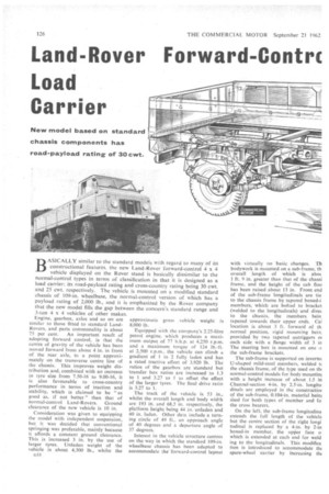
New model based on standard chassis components has road-payload rating of 30 cwt.
BASICALLY similar to the standard models with regard to many of its constructional features. the new Land-Rover forward-control 4 x 4 vehicle displayed on the Rover stand is basically dissimilar to the normal-control types in terms of classification in that it is designed as a load carrier: its road-payload rating and cross-country rating being 30 cwt.
and 25 cwt. respectively. The vehicle is mounted on a modified standard chassis of 109-in, wheelbase, the normal-control version of which has a payload rating of 2,000 lb., and it is emphasized by the Rover company that the new model fills the gap between the concern's standard range and 3-ton 4 x 4 vehicles of other makes.
75 per cent. An important result of adopting forward control, is that the centre of gravity of the vehicle has been moved forward from about 4 in. in front of the rear axle, to a point approximately on the transverse centre line of the chassis. This improves weight distribution and, combined with an increase in tyre size from 7.50-16 to 9.00-16, it is also favourable to cross-country performance in terms of traction and stability, which is claimed to be "as good as, if not better" than that of normal-control Land-Rovers. Ground clearance of the new vehicle is 10 in.
Consideration was given to equipping the model with independent suspension, but it was decided that conventional springing was preferable, mainly because it affords a constant ground clearance. This is increased 3 in. by the use of larger tyres. Unladen weight of the vehicle is about 4,100 lb., whilst the GI8 8,000 lb, Equipped with the company's 2.25-litre petrol engine, which produces a maximum output of 77 b.h.p. at 4250 r.p.m. and a maximum torque of 124 lb.-ft. at 2,500 r.p.m., the vehicle can climb a gradient of 1 in 2 fully laden and has a rated tractive effort of 3,920 lb. The ratios of the gearbox are standard but transfer box ratios are increased to 1.3 to 1 and 3.27 to 1 to offset the effect of the larger tyres. The final drive ratio is 3.27 to 1.
The track of the vehicle is 53 in., whilst the overall length and body width are 193 in. and 68.5 in. respectively, the platform height being 44 in. unladen and 40 in. laden. Other data include a turning circle of 49 ft., an approach angle of 40 degrees and a departure angle of 37 degrees.
Interest in the vehicle structure centres on the way in which the standard I09-in. wheelbase chassis has been adapted to accommodate the 'forward-control layout
with virtually no basic changes. Th bodywork is mounted on a sub-frame, th
overall length of which is abot. 1 ft. 9 in. greater than that of the chassi frame, and the height of the cab floo has been raised about 13 in. Front end of the sub-frame longitudinals are tie.
to the chassis frame by tapered boxed-i members, which are bolted to bracket (welded to the longitudinals) and diret to the chassis, the members bein, tapered towards their upper ends. Cal location is about 3 ft. forward of tii.
normal position, rigid mounting bein. provided by two tapered outriggers oi each side with a flange width of 3 in The steering box is mounted on one the sub-frame brackets.
The sub-frame is supported on invertec U-shaped mild-steel members, welded tc the chassis frame, of the type used on thi normal-control models for body mountim with a height increase of about 1.5 in Channel-section 4-in. by 2.5-in. longitu dinals are employed in the constructiot of the sub-frame, 0,104-in, material beim used for both types of member and fa the cross bearers.
On the left, the sub-frame longitudina extends the full length of the vehicle but the centre section of the right longi tudinal is replaced by a 4-in. by 2-in boxed-in member, the upper face o which is extended at each end for weld ing to the longitudinals. This modiflca tion is introduced to accommodate thi spare-wheel carrier by increasing tht
nrance between the sub-frame and iassis members by some 3 in., the num:r of U-shaped support members being cluced to 10 on the right side. compared ith 12 on the left. The spare wheel is tained by a hinged clamp with screwpe tensioner and is supported on a cross arer of the chassis frame. First and cond cross-members of the sub-frame e of 4-in. by 1.75-in. and 4.5-in, by in. channel-section respectively. At the ar. a 9-in. by 2-in. angle-section mem k employed, the longer side of which flush with the rear ends of the longidinals. and is bolted to brackets welded the rear chassis-frame cross bearer. The suspension remains basically unianged with regard to spring-length and c-centre distance, but both the front id :.car springs have a higher rate than e standard type. Telescopic shock isorbers are fitted all round.
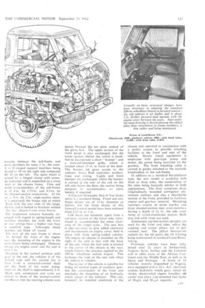
The rear of the seat frame is about in. behind the front of the engine iver, the mounting of the engine in the iassts frame being unchanged. Distance :twcen the engine cover and the seat is tout 1 in.
Mounted in the normal position with gad to the cab; the radiator is of the ardard type and the covvled fan is iven from a universal-jointed shaft om the front of the water pump. -:.ngth of the shaft is approximately 2 ft. Dash unit, windscreen and vents are enticat to those of the normal-control mil-Rover, but the steering column now
passes through the toe plate instead of the glove box. The upper section of the front panel is also unchanged, but the lower section (below the vents) is modified to incorporate a short " bonnet " and a forward-mounted grille, which is located about 13 in. in front of the dash. The bonnet lid gives access to the radiator, brake fluid container, toolbox, fuses and wiring. Lights and front bumper are unchanged, whilst the battery is carried at the rear of the cab on the left side below the floor, the carrier being designed to accommodate an extra battery if required.
A Clayton Dewandre Mot-A-Vac brake servo is a standard fitting. Front and rear brake drums are of 11-in, diameter as before, but the front drums of this forward-conlrol model have been widened from 2.25 in. to 3 in.
Cab doors are standard, apart from a cut-away section on the lower side, introduced to accommodate the extra clearance of the larger tyres. The seat box is also cut-away to give added clearance and incorporates an engine cover, held in place with three spring-loaded catches. The engine air cleaner is mounted on the right of the unit in line with the back of the cab, whilst the fuel tank is located in the centre of the chassis at the rear, which follows the practice applied to the 109-in wheelbase station wagon. This increases the load on the rear axle when the vehicle is unladen.
The layout of the vehicle is suitable for fitting all normal types of auxiliary gear. but the construction of the front end precludes the mounting of an hydraulic winch ahead of the radiator. This can, howevee, be installed amidships in the chassis and operated in conjunction with a pulley system to provide winching facilities at the front and rear of the vehicle. Dowty winch equipment is employed with gear-type pump and motor, the pump being mounted on the gearbox. The front winching cable is carried in guides attached to the nearside longitudinal of the sub-frame.
In addition to a standard flat-platform type, the new model is available with fixed or drop sides, the construction of the sides being basically similar in both applications. The floor comprises three longitudinally mounted corrugated aluminium sections and also a detachable section at the front, provided to facilitate engine and gearbox removal. Mounting members consist of seven top-hat and three channel-section steel cross-members having a depth of 2 in., the side raves being of rolled-aluminium section. Both pop and solid rivets are used.
Aluminium top-hat-section uprights are used for the front and sides, whilst the capping and corner pillars are of galvanized steel. The pillars incorporate sockets for the tilt posts, the tilt framing being constructed' of standard Land-Rover tubing.
Prototype vehicles have been fully tested over 21, years in Switzerland, Nigeria, Syria, Jordan and the Lebanon and in other parts of the African Continent and the Middle East, as well as in Spain and Portugal. A batch of 15 vehicles recently dispatched to Nigeria, were equipped with a 12-v. A.C. electrical system, hydraulic winch gear, raised air intake, dustproofed engine breather, oil cooler and extra side-mounted fuel tanks of 10-gal. and 28-.;a1. capacity.