


PERKINS Ii iCES NEW
Page 26
Page 27
Page 28

If you've noticed an error in this article please click here to report it so we can fix it.
7.4-LITRE VI OIL ENGINE
AeroflowPrinciple, Tested and Wellproved in Succesiful"P" -series Engines, Now Applied to Larger Unit With an Output of 115 b.h.p.
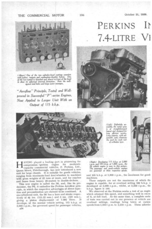
HAVING played a leading part in pioneering the compression ignition engine for moderatecapacity commercial vehicles, F. Perkins, Ltd., Queen Street, Peterborough, has now introduced a new unit for large chassis. It is suitable for goods vehicles, ranging from maximum-load four-wheelers to machines with gross weights of 22 tons or more, and for coaches and buses from luxury 26-seaters to double-deckers.
This new engine is called the S6, and, like its predecessor, the P6, it embodies the Perkins Aeroilow principle, in which the respective advantages of direct injection and precombustion are claimed to-,be .combined. A six-cylindered unit, the S6 has a bore and stroke respectively of 4# ins. (111.12 mm.) and 5 ins. (127 mm.), giving a piston displacement of 7.392 litres. It develops, at the normal vehicle setting, 115 b.h.p. at 2,000 r.p.m., the governed speed for passenger vehicles,
and 105 b.h.p. at 1,800 r.p.m., the maximum for good: machines.
These outputs are not the maximum of which. th( engine is capable, for at overload setting 132 b.h.p. developed at 2,000.r.p.m., whilst, at 2,250 r.p.m., tin b.h.p. figure is 144.
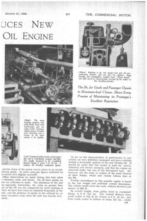
We observed at the Perkins. works a test of an engin. which attained this speed, and something well in exces of it, at full load. At the same time, a complete serie: of tests was carried out in our presence at vehicle an overload settings, readings being taken at variou: speeds from 1,000 r.p.m. to 2,250 r.p.m. These afforde( precise check of the power curves given in an accomanying graph. In some cases the figures indicated by se curves were slightly exceedek Other observations we made 'during this trial relate ) vibration, noise and smoke. On all three points we ave no criticisms to make. The steadiness of the unit 'as especially noteworthy, the noise no greater than sat of the P6 (on the comparatively quiet running of hich we have had cause to comment frequently in the ast), and the presence of smoke in the exhaust by no teans excessive, even when the unit was heavily over • aded. So far as this demonstration of performance is concerned, we were definitely impressed and have certainly formed a favourable opinion of the new Perkins S6. It should be noted that this model is built for vehicle, industrial and marine purposes, and that the engine we observed under test was of the last-named type. All, however, are the same in respect of the main features of their design, which also closely follows that of the P6. • • • Further resemblance to this popular engine is found in the low weight and moderate overall dimensions. The vehicle model turns the scale, without flywheel and starter, at 930 lb.
Its overall length, from pulley front to crankshaft flange, is 3, ft. 215T ins. The vertical distance from crank centre to top of air cleaner is 2 ft. 2i ins., and from crank centre to bottom of sump 14 ins., whilst
the overall width of the sump and body of the unit nowhere exceeds 19 ins.
The S6 is offered complete with flywheel and housing, which can be machined to suit various types of clutch and gearbox. A 24-volt starter, an exhauster, a C.A.V. transfer pump and two fuel filters are also included as standard ; the price thus equipped is E595.
From reliability and durability angles, the big margin between service and maximum outputs (the former is only 87 per cent. of the latter), and between governed and maximum (3,000 r.p.m.) speeds, is noteworthy, as also are the facts that all bearings are of generous dimensions and that provision is made for conveying local heat away from the main bearings by a system of water cooling.
Both the upper and lower halves of the main and big-end bearings are of lead bronze and steel backed. Of the former bearings, there are seven which carry a fully balanced crankshaft of nickel-chrome-molybdenum steel. This has integral balance weights, is heat treated and is hardened by the Tocco process.
Thorough Cooling Arrangements.
Maximum cooling of the head, particularly the atomizer surrounds, is ensured by introducing the cooling water under pressure at six points. Around the cylinders are full-length jackets, through which water circulates by thermo-siphon action'. This part of the cooling system is extended to the main-bearing seatings.
Whilst the block and crankcase top half are formed as a single. chronlium-iron casting, the head, of similar material, comprises two units. It carries the rockers, which are actuated, via long tappets, by a high camshaft mounted in four large bearings on the off side. Aluminium-alloy castings are employed for the sump and valve-gear and timing-case covers.
Inlet valves, with heads of considerably greater size than those of the exhausts, are a salient feature, the respective overall diameters being 2k ins, and lt ins. The object of the big inlets, of course, is to improve volumetric efficiency. Both valves are of special steel, and no masks or deflectors are used.
Spherical in shape, the combustion chambers are formed half in the head casting and half by detachable steel caps. Accessibly located in the tops of the heads, and having bronze seatings, the atomizers each inject two sprays—one into the combustion chamber and one into the cylinder.
This is part of the Aeroflow scheme and results in easy starting, high speed and economy. Because the spray holes are large, fuel pressure is relatively low and wear and tear are minimized.
Efficient Piston Design.
Of a specially light aluminium alloy, the flat-topped pistons contain ample metal in the crowns for heat dispersal, whilst generous ribs transmit explosion pressure to the bosses. There are three pressure rings, the topmost being well below the level of the crown, so that it is not exposed to the full heat of combustion. In addition, there are two scrapers.
Large, fully floating gudgeon pins, working in bronze bushes, carry the connecting rods, which are H-section chrome-molybdenum-steel stampings, their weight being as low as is possible consistent with strength.
Incidentally, when reboring and new pistons become necessary, there is ample metal in the main casting to permit the fitting of sleeves, if desired. The bores are finished by honing. No doubt an important contribu a26 tion to the success of the engine is made by the wc11thought-out ribbing of the main casting, which gives the complete assembly excellent rigidity and resistance to distortion.
Of straightforward layout, the distribution gear at the front comprises a triple-roller chain, sprockets, dampers and automatic tensioner. The drive is taken to the camshaft and injection-pump shaft. From this, a separate triple-roller chain transmits it to the lower auxiliary shaft, which runs the dynamo and water pump. Completing the main timing case is a pressedsteel cover, whilst an aluminium housing encloses the second chain A pair of spiral gears on the upper auxiliary shaft drives the submerged oil pump, which impels oil at high pressure to main, big-end and camshaft bearings and rocker and timing gears. Lubricant enters the pump via a large and readily detachable strainer and passes from the pump to a pressure cleaner, mounte4 externally on the near side of the engine. Thence i flows to a cast-in gallery, from which drilled oilway take it to the main bearings. A branch passage i provided for the remainder of the supply. Special provision is made for ventilating the crank case. Under all running conditions, filtered air drawn through, extracting all vapours. The arrang( Ment maintains a constant depression within the crath case, thus precluding the escape of fumes which migl penetrate into the driver's cab, or, in the case of passenger vehicle, into the saloon.
Control of the C.A.V. injection pump, as on the PI is by pneumatic means, the accelerator pedal bein coupled only to a throttle in the air intake. Timir is entirely automatic. Apart from the stopping leve the air throttle is the only control. It is housed in C.A.V. venturi inlet, on which is mounted the larf oil-bath air cleaner.
With regard to the installation of the Perkins engine, provision is made for attaching rear bracke to the bell housing, whilst there are facings on bo. sides of the main casting, adaptable by suitable fixin for single or two-point front mounting.