


FREE WHEEL Published Patent Specifications A FREE wheel which contains
Page 74
If you've noticed an error in this article please click here to report it so we can fix it.
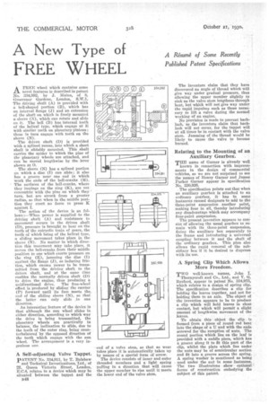
some novel features is described in patent No. 334,992, by J. Mains, of 8, Grosvenor Gardens, London, S.W.1. The driving shaft (A) is provided with a bell-shaped portion (B), which has an internal flange (S) and an extension of the shaft on which is freely mounted a sleeve (N), which can rotate and slide on it. The bell (B) has internal teeth of the helical type, which engage at E -with similar teeth on planetary pinions' these in turn engage with teeth on the sleeve (N).
The driven shaft (D) is provided with a splined recess, into which a short shaft is slidably mounted. This shaft carries the spider to which the pins of the planetary wheels are attached, and can be moved lengthwise by the lever shown at 0.
The sleeve (N) has a splined portion on which a disc (I) can slide; it also has a groove near one end in which work the ends of the bell-cranks (M). The surfaces of the bell-cranks, where they impinge on the ring (K), are not concentric with the pins on which they turn, but are struck from a greater radius, so thai when in the middle position they exert no force to press K against I.
The action of the device is as follows :—When power is supplied to the driving shaft (A) and resistance to movement occurs in the driven shaft (D), pressure is brought to bear on the teeth of the epicyclie train of gears, the teeth of which being of the helical type, a sliding movement takes place in the sleeve (N). No matter in which direetion this movement may take place, it moves the bell-cranks from their middle position to one which exerts pressure on the ring (K), jamming the disc (I) against the flange (J), so inducing friction, which causes power to he transmitted from the driving shaft to the driven shaft, and at the same time enables the normally driven shaft (D) to drive the engine, thus producing a unidirectional drive. The free-wheel effect is produced by sliding the carrier (P) forward until its face meets the emrl of the sliding sleeve (N), so that the latter can only slide in one direction.
• An interesting feature of the device is that although the sun wheel slides in either direction, according to which way the drive is being transmitted, the planetary wheels are practically in balance, the inclination to slide, due to the teeth of the outer ring, being counterbalanced by the opposed direction of the teeth which engage with the sun wheel. The arrangement is a very ingenious one.
A Self-adjusting Valve Tappet.
PATENT No. 334,911, by T. Balshaw and Technical Investigations, Ltd., of 27. Queen Victoria Street, London, E.C.4, relates to a device which may be situated between the tappet and the
B48
end of a valve stem, so that as wear takes place it is automatically taken tip by means of a special form of screw.
The device consists of inner and outer threaded members and a light spring pulling in a direction that will cause the upper member to rise until it meets the lower end of the valve stem.
The inventors claim that they have discovered an angle of thread which will give way under gradual pressure, thus allowing the upper member slightly to sink as the valve stem lengthens through heat, but which will not give way under the rapid impulses such as those necessary to lift a valve during the normal -working of an engine.
No provision is made to prevent backlash, as the inventors claim that backlash will not occur, for the tappet will at all times be in contact with the valve stem. Jamming of the thread would be likely to cause the valve to become burned.
Relating to the Mounting of an Auxiliary Gearbox. •
THE name of Garner is already well known in connection with improvements in the design of commercial vehicles, so we are not surprised to see the names of Henry Garner and James Parker Garner appear in specification No. 830,026.
The specification points out that when an auxiliary gearbox is attached to an ordinary gearbox, it has in some iustances caused designers to add to the three-point suspension another point, making four in all, thereby introducing any disadvantage which may accompany four-point suspension.
The present invention appears to consist of allowing the usual gearbox to re"main with its three-point suspension, fixing the auxiliary box separately to the frame and introducing a universal coupling between it and the shaft of the ordinary gearbox. This plan also allows the rapid removal of the subsidiary box if it be desired to dispense with its use.
A Spring Clip Which Allows More Freedom.
TWO well-known names, John I.
Thornycroft and Co., Ltd., and V. G. Ballard, appear in patent No. 334,976, which relates to a design of spring clip. The specification describes a clip for bolding the leaves together, and not for holding them to an axle. The object of the invention appears to be to produce a clip which will hold leaves in close contact, but which will permit a slight amount of lengthwise movement of the leaves.
To obtain this object the clip is formed from a piece of round rod bent into the shape of a U and with the ends screwed for the reception of nuta. The round portion which lies on the leaf is provided with a saddle piece, which has a groove along it to fit this part of the clip, whilst the plate which lies under the nuts may be of semicircular section and fit into a groove across the spring. A spring washer is mentioned as being used under the nut in some instances. The two illustratons show optional forms of construction embodying the subject of this patent