


A REVOLVING CYLINDER ENGINE.
Page 24
If you've noticed an error in this article please click here to report it so we can fix it.
A Résumé of Recently Published' Patents.
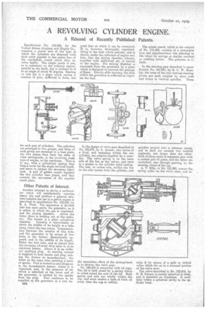
Specification No. 119,460, by the United States Airplane and Engine Co., concerns a power unit of the type in which the cylinders are disposed with their axles parallel to the centre line of the crankshaft, round which they revolve .bodily. The. single crank is not, as is customary on the ordinary engine, parallel to the shaft, but is inclined to it at an angle of about, 45 degrees. Bearing on this pin is a plate which carries a number of pins, spherical in form, One for each pair of cylinders. The cylinders are arranged in two groups, and those of each group are mounted in a base plate, the two plates then form the sides of what corresponds, in the revolving shaft type of engine, to the crankcase. That is to say, with a cylindrical casting they form a cover for the single inclined crank, and serve to contain the necessary lubricant. A pair of guides couple together the two cylinder base plates, and they restrain the movement of the angular crank plate.
Other Patents of Interest.
Another attempt to devise a carburetter which will satisfactorily vaporize heavy oils and produce a gaseous mixture suitable for use in a petrol engine is described in specification No. 118,622, by E. A. West. The apparatus is divided into two main parts, the generator, as it is called, in which the gas is vaporized, and the mixing clusnaher. About the latter there is nothing out of the ordinary. The former is a plain cylindrical chamber. Crossing it transversely at about the middle of its height is a tube along which the fuel enters. Communication between the interior of this tube and the generator is by means of two holes in the former, diametrically opposed, and in the middle of its length. Below the fuel tube, and so placed that the incoming oil must drop upon it, is an electrical heater. Above it is an ordinary sparking plug. At starting current is supplied to both heater and plug, raising the former to incandescence, the latter at the same time emitting a train of sparks. Fuel is turned on and drops on to the incandescent heater, where it is vaporized, and, in the presence of 'air which is admitted at the lower end of the generator, is ignited by the sparks from the plug. Fuel continues to be supplied to the generator at a rate be
yond that at which it can be consumed. 'At is, however, thoroughly , vaporized owing to the heat which prevails, and is drawn under the influence of engine suction, into the mixing chamber whence, together with additional air, A travels to the engine. The mixing chamber is separated from the generator by a plate Which is designed to prevent the passage of flame. Shortly after starting, the heat within the generator is sufficient to vaporize the fuel.
In the design of valve gear described in No. 132,070, by A. Anzani, two valves of a kind, and operating within the one cylinder, are coupled together by a CTOSSb-ar. The valve spring is on the same side of the bar as the valves, and rests in a pocket in the cylinder head casting. The cam, or rocker arm, strikes the bar on the side remote from the cylinder, and
the immediate effect of the arrangement is to shorten the valve gear.
No. 122,416 is concerned with oil cups. The lid is held closed by a, spring which is coiled round the axle of the lid. Both spring and axle are wholly within the cup, and must receive a bath of fresh oil every time the cup is refilled. The splash guard, which is the subject of No. 131,929, consists of a pneumatic tyre and supplementary rim attached to the wheel by springs or similar resilient or yielding means. The patentee is C. Lean.
In the steering gear described in specification No. 131,967, by R. C. V/. Horsley, the arms of the two vertical steering pivots are each coupled by short rods and levers to vertical spindles. These spindles project into a common casing, and to each are secured two toothed segments, one larger than the other. Both of these pairs of segments gear with a central pair of gears, and the latter are controlled, also through gearing, by the steering wheel of the car.
A. T. Ellis, in No. 131,983, screws the spring collar on the valve stem, and re
tains it by means of a split or slotted collar which fits on to a recessed portion • of the valve stem.
The valve described in No. 132,053, by D. E. Turner, is mainly spherical in form,, and is mounted on trunnions. It oscillates within a spherical cavity in the cylinder head.