


An Hydraulic • •
Page 34
If you've noticed an error in this article please click here to report it so we can fix it.
Spare-wheel Lifter
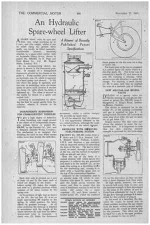
ASPARE wheel, with its tyre and tube, may weigh anything up to 3 cwt., and this weight, whilst it an be rolled along the ground falrly easily, can hardly be lifted manually. Considerable interest, therefore, attaches to a spare-wheel carrier, with an hydraulic lifting device, shown in patent No, 539,624, by E. Page and Ford Motor Co.. Ltd., 88, Regent
Street, London, W.1. .
. In an accompanying sketch the device is shown in the• lowermost position. It consists of a triangulated framework pivoted to the chassis at the point 2. Fronr another' pivot extends an hydraulic ram (4) which is operated by a hand pump (not shown). To lift the wheel the pump is operated, and the ram, in extending, turns the frame about its pivot until crossbar 3 reaches the clamp (1), after which the latter is tightened up. The wheel is secured in the cradle by means of a spider and central bolt.
Lowering is accomplished by allowing the fluid to escape gently from the cylinder, whence it returns to its reservoir.
INDEPENDENT SUSPENSION FOR CROSS-COUNTRY VEHICLES
T°give a high degree of deflection when travelling over rough ground is the object of an independent-suspension system shown in patent No. 539,597, by the Daimler Co., Ltd., and C. Simpson, Daimler Works, Coventry. The mechanism is so designed that doubling the load on any Wheel causes rather more than double the deflection.
Each stub axle is pivoted on a pair of links (4 and 5) the inner ends of which are hinged to the frame. A helical spring (1) takes the weight, and rests on a pivoted platform which remains at all times normal to the spring axis.
In the position of light load as shown rm the left, the top link (5) is at an angle approaching 90 degrees to the spring, in which position the latter
effects its greatest leverage. At all other positions the leverage is lessened in accordance with the length of the centre distance (2) and thus the &flee
' tion-to-load ratio is increased. A check wire. (3) limits the downward
movement, whilst a rubber bumper (6) provides an upper stop.
It will be observed that the distance 7 is not appreciably different in the two wheel positions, although the angle to the vertical of the wheel clionges.
PRODUCER WITH IMPROVED FUEL-FEEDING SYSTEM
DATENT No. 539,440 comes from J.
Hales and C.U.R.A. Patents, Ltd., 9, Rickett Street, Fulham, London, S.W.6, and discloses a gas producer with an improved method of controlling the form of the fire. The fuel is introduced, as usual, through a cover plate at the top, and the bottom is equipped with an ash-pit and door.
Near the top of the body is a conical member (12) which serves tWo purposes ; it collects the gas generated and leads it to the outflow (1), at the sane time acting as a. throttling device for the descending fuel, causing it to settle with a basin-like space (11) at the top ol the combustion chamber.
Adjacent to the combustion zone is an annular ledge (4) which, in combination with space 11, tends to segregate the larger pieces towards the centre, and thus to ensure that the zone of maximum reaction is well in the centre. Air enters via a .water vaporizer (2) and flows around a heated jacket (3), whilst the resultant steam passes to the fire zone via a. ring of holes (10).
The lower part of the fire is contained in a. conical space (6) under Which is a disc-like grate (8). The latter can be rotated by a handle (7) and there is an arm (9) carrying a bearing, which serves as an ash disturber to assist discharge. For starting, a small dry-air jet (5) is used ; here May be inserted_ the nose of a domestic pair of bellows.
NEW AIR-COAL-GAS MIXING VALVE
DETAILS of a gas-air valve for L./vehicles running on coat-gas are contamed in patent No. 539,570, from G. Mangoletsi, 4, King's Road, Ashtonon-Mersey, Cheshire.
The device is mounted on to the intake (7) of the existing carburetter and gas is supplied to pipe 4. A spring-loaded disc-valve (5) controls an outer ring of air hOles (2) and an inner set qf gas holes (3).
Engine suction lifts this valve and allows the mixture to enter the carburetter inlet. It is important-to note that for slow running mixture strength is governed by the knife-edges
(1) on the disc-valve, as they are then only a short distance from their seats. At high speeds, however, the valve is moved well away from its seat, and the mixture strength is then determined by the areas of the orifices (2 and 3). Ports 2 are adjustable by ring 8, whilst the gas flow through passages 3 is determined by the position of plug 9. In the event of a back-fire, the discvalve (5) would be forced into its closed position isolating the gas supply from the flame, whilst a second springclosed ,valve (6) would be blown open by the pressure. This valve can also be fixed by a pin in the open position, if it be desired to run on petni...