 1
1 2
2 3
3 4
4 5
5 6
6 7
7 8
8 9
9 10
10 11
11 12
12 13
13 14
14 15
15 16
16 17
17 18
18 19
19 20
20 21
21 22
22 23
23 24
24 25
25 26
26 27
27 28
28 29
29 30
30 31
31 32
32 33
33 34
34 35
35 36
36 37
37 38
38 39
39 40
40 41
41 42
42 43
43 44
44 45
45 46
46 47
47 48
48 49
49 50
50 51
51 52
52 53
53 54
54 55
55 56
56 57
57 58
58 59
59 60
60 61
61 62
62 63
63 64
64 65
65 66
66 67
67 68
68 69
69 70
70 71
71 72
72 73
73 74
74 75
75 76
76 77
77 78
78 79
79 80
80 81
81 82
82 83
83 84
84 85
85 86
86 87
87 88
88 89
89 90
90 91
91 92
92 93
93 94
94 95
95 96
96 97
97 98
98 99
99 100
100 101
101 102
102 103
103 104
104 105
105 106
106 107
107 108
108 109
109 110
110 111
111 112
112 113
113 114
114 115
115 116
116 117
117 118
118 119
119 120
120 121
121 122
122 123
123 124
124 125
125 126
126 127
127 128
128 129
129 130
130 131
131 132
132 133
133 134
134 135
135 136
136 137
137 138
138 139
139 140
140 141
141 142
142 143
143 144
144 145
145 146
146 147
147 148
148 149
149 150
150 151
151 152
152 153
153 154
154 155
155 156
156 157
157 158
158 159
159 160
160 161
161 162
162 163
163 164
164 165
165 166
166 167
167 168
168 169
169 170
170 171
171 172
172 173
173 174
174 175
175 176
176 177
177 178
178 179
179 180
180 181
181 182
182 183
183 184
184 185
185 186
186 187
187 188
188 189
189 190
190 191
191 192
192 193
193 194
194 195
195 196
196 197
197 198
198 199
199 200
200 Rubber-bushed running_.gear overhaul
Page 152
Page 153
Page 154
If you've noticed an error in this article please click here to report it so we can fix it.
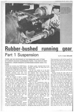
Part 1 Suspension by R. D. Cater AMInstBE THERE are currently some 70,000 Rubery Owen R type suspensions of single, tandemand triple-axle configurations running on the highways of the world. The R type has been in production since 1958 and many of the assemblies produced must now have covered hundreds of thousands of miles and be ripe for overhaul.
With this thought in mind I recently undertook to overhaul an R type tandem unit. Who better, I thought, than the makers to supervise the job, for although they do not get involved in trailer overhaul they must know better than anybody how the gear should be 'put together. And so I arranged to do the overhaul under their supervision using only the minimum amount of tools which might be found in any small fleet workshop. Other than a special jig which can be hired from Rubery Owen at a nominal fee and which is used to ream the brake anchor spiders, and two box spanners, no special tools were used.
The running gear used as a guinea pig was by no means worn out. It had covered 170,000 miles and had received no attention other than having its brakes relined.
Several components, however, showed that even in an organization which obviously gave its equipment constant attention of the highest quality, important items of adjustment were either not taken care of or not understood.
The job was earned out in the most economical manner both in terms of labour and material. Only where parts were considered not to have a further usoru/ lease of life were they replaced. Where there was a knack used in the assembly plant of Rubery Owen which did not entail the use of expensive equipment, then this was applied to the repair.
Now my first consideration when undertaking an overhaul is to ensure that the subject is in a reasonably clean condition. Fitters will obviously work more efficiently on a clean machine; they can see defects that would otherwise be hidden even from the most critical and experienced eyes, and one does not want road dirt to fall over the wheel bearings during the final stages. So a good steam clean is probably the best investment one can make when commencing an overhaul of any kind.
After ensuring the unit. was clean, the frame was jacked and supported to remove all imposed weight from the suspension and we commenced removing the balance beam assembly. The two locking bolts passing through the beam and pin were tackled first. These presented us with the first snag for we found nuts seized solid on the bolts and our tool kit did not boast any special tools to take account of their awkward positioning. I wasted about half an hour trying to remove the bolts by conventional methods but finally resorted to a 41b. hammer and cold chisel to split the nuts, which Were to be scrapped anyway, and cut the cost of labour involved.
Passing through the outer ends of the pivot shaft and the flats of the hexagon nuts securing it are two 0.25in. bolts. These must be removed and the pivot nuts slackened with a 4in. AF tube or box spanner. It is unlikely that one of these will be found in most small workshops, and the same might be said of the combination box-spanner used later on for the hub nuts. But both these tools can be purchased complete with tommy-bar from Rubery Owen Rockwell at a cost of E5 each. Do not be tempted to use a Stilson wrench or a large-size shifting spanner for this job. The end result if you do will be smashed fingers, chewed up flats on the nuts and most certainly incorrect torque application to the finished job.
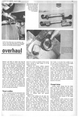
The beam-locking bolts from which we cut the nuts had been left in the assembly to provide a positive lock on which to jar the retaining nuts and achieve the first movement. This done, they could be taken out and it remained only to remove the pivot pin from the balance beam. It is impossible, I have found to my cost, to do this with a hammer and drift no matter how big the hammer. The resilience of the rubber bushes simply absorbs any shock treatment one can apply in this direction. Quenching with soapy water and finally easing oil had equally little effect. And so after going through all the agonies of the ill-equipped shop and proving that there was no future in the "brawny approach", a medium-sized and simple two-legged hub-puller was applied to the end of the shaft and screwed up, whereupon the shaft popped out with no trouble.
The solid and adjustable radius rods which locate the axles are bushed at each end with a pair of half-bushes. These were removed quite easily once the retaining bolt was taken out because their interference fit is achieved only when they are compressed by the retaining bolt assembly.
Thread condition There remained only the mechanical units of the actual suspension to be inspected. Provided there is not an excessive degree of slack in the fit between the balance beam pivot pin and the beam, then this cornponent can quite safely be refitted for a further term of service and on this occasion they were. Only the condition of the threads and the fact that they may be wasted, by having come into contact with the frame in the event of the rubber bushes being badly worn, can warrant changing the radius rod bolts. The self-locking nuts, however, should
never be re-used, as retention of the correct torque settings at these points is of the utmost importance.
Refitting the various rubbers required little engineering knowledge other than being able to use a torque wrench. On every working point throughout the suspension, the torques have been carefully set to ensure that the correct compression is maintained on the rubber without distorting or causing other damage to the forgings which carry it.
A box of french chalk powder is the only addition to the tool kit which one needs to assemble the suspension. All bushes should be thoroughly dusted with chalk before fitting. This ensures that they travel right home on, or into, their respective housings before compressiot1 and, therefore, expansion takes place. Never in any circumstances should grease or oil be used as a lubricant as this will shorten the life of the rubber and cause untold problems in the shape of shifting axles and general misalignment.
Slipper-ended springs do not play any part in axle alignment. But if springs are being replaced, and especially if a local blacksmith does the reconditioning, the physical dimensions of the units used should be checked The two points to watch here are the measurement from axle pad to a straight line taken across the two ends which is approximately 7.5in, and that the flat section in the centre of the spring is long enough to clear the actual saddle carrying
the U bolts. A too-short flat is liable to upset one's torque setting on the U bolts which in turn will lead to premature failure.
As a result of investigations in the operating field which have been carried out by Rubery Owen service-department members, it is now recommended that the adjustable radius rods be fitted to the offside of the trailer. The reason for this is that in the nearside position, the screwed assembly is severely attacked by corrosion caused by water, salt, grit and other contaminants which are held in the greatest concentration nearest to the kerbs.
Changed design
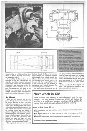
Another design change that has taken place is that the adjustable radius rod is now solid instead of tubular, and it carries male leftand right-hand threads which screw into forged female ends. The solid rod has a machined hexagon to facilitate adjustment and the female ends are equipped with double-locking bolts instead of the single bolt formerly used.
Two important points should be noted when assembling these items. The torque setting for the two clamping bolts is now set at 701b.ft and not 130Ib.ft as on the previous single-bolted types, and the open jaws of the clamp should be arranged so that they point to the ground and do not form a water trap. The retaining bolts securing the torque arms should be tightened to a torque wrench setting of 1751b.ft, and this item should-be cheeked frequently once the vehicle is placed in service.
In assembling the balance beam it was necessary to strip both the nuts from the shaft. The new rubbers could not be inserted in the carrier and the shaft passed through afterwards. It was impossible to align the locking bolt holes in the beam and the pin Once the rubbers were fully home in the housing, for contraction of the inner diameter had already begun and the pin was held firmly, resisting all attempts to move it.
Not tightened
With the nuts removed, the pin was passed through the beam and carrier and the locking bolts put in place. Their nuts and washers were put on, but not tightenec4 at this stage. The main rubbers, well dusted with chalk, were then fully inserted over the shaft and into their respective housings with the retaining washers and nuts placed in position and gently nipped onto the rubbers making absolutely sure that these had bottomed in the housing and that they had not picked up on the shaft. The locking bolts through the beam and shaft were then tightened and the shaft retaining nuts pulled up equally to a torque setting of 3001b.ft.
The original pin and nuts were used and the holes through the flats of the nuts and those in the pin were aligned and the outer 0.25in. locking bolts passed through and tightened. If new components are used then it is necessary to drill through with a 0.25m. clearance drill. That completed the overhaul of the suspension with the exception of checking the axle U bolts for tightness. The torque setting of these is 2251b.ft.
Two other points occur to me here. If new springs are being fitted, do not forget to clean any preserving grease from the areas covered by the axle pad and the U bolt saddle, and remember that the end of the spring with a small lip on the underside of the fourth leaf always rides in the balance beam.
In the second part of this report, next week, I shall describe the overhaul of hub and mechanical brake equipment.