


AN ENTIRELY NEW BEAN CHASSIS.
Page 63
Page 64

Page 65
If you've noticed an error in this article please click here to report it so we can fix it.
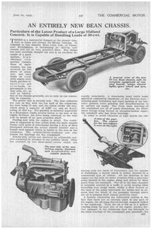
Particulars of the Latest Product of a Large Midland Concern. It is Capable of Handling Loads of 30-cwt.
THERE is a substantial demand at the present time, both at home and abroad, for 30-cwt. vehicles. In response to this demand, Bean Cars, Ltd., of Tipton, near Birmingham,. is introducing an entirely new chassis laid out on very practical lines. The design has been carefully thought out and is an excellent example of a good. modern, h i g hefficiency c naDierdal °"chassis. Ease of mainten-ance, too, has received its full share of attention, and such items as complete engine over-. hauls, gearbox in spection and over hauls, replacements to the rear axle, etc., as well as lubrication of the chassis generally, are as easy as can reasonably be expected.
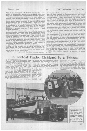
The power unit is entirely new. The four cylinders are cast en bloc with the top half of the crankcase, the bore being 75 mm. and the piston stroke 130 mm., which gives a capacity of 2,297 c.c. and an R.A.C. rating of 13.9 h.p. The.gearbox is mounted separately in a flitch-plate cmdle several inches to the rear of the engine flywheel, the drive being conveyed to the rear axle by means of an open propeller shaft. Dealing now with the engine in detail. The crankcase is supported at four points from the main chassis frame, each point of attachment having a strip of fibre interposed between the actual chassis member and a looped steel support which is bolted to the arm on the crankcase. The cylinder-block-crankcase unit also houses the bearings for the crankshaft.
Side-by-side valves are operated by. adjustable tappets contained in recesses in the cylinder block. .They are enclosed by two sheet-metal covers which are readily detachable. A detachable head (with hemispherical combustion chambers—of the Ricardo type— ensuring good turbulence and rapid burning of the mixture) permits valve grinding and decarbonization to be carried out easily. The three main bearings of the crankshaft are all of ample dimensions, the whitemetal linings being backed 'by phosphor-bronze cages; the camshaft also has three bearings.
In order to avoid vibration at high speeds the con fleeting rods are made of Duralumin and the pistons of aluminium, a layout which is rather unusual in a commercial type of vehicle. All the bearings in the engine are fed with oil under pressure from a gear-type pump located in' the engine sump and driven by skew gears from the camshaft. The oil in the base chamber is normally covered by a baffle to avoid surging when travelling over rough roads, whilst a filter located at the base of the pump surrounds the intake and so ensures that the whole of the passages through which the oil is pumped shall remain perfectly clear. A feature concerning' the lubrication system is the fact that there are no internal pipes in any part of the engine, the oil being forced through channels drilled in the crankcase.. Thus, the oil is led up to a gallery running along the near side of the engine, whenee.further passages in the crankcase lead the lubricant to the main bearings of the crankshaft and camshaft ; the
big-end bearings of the connecting rods take their supply through channels drilled within the crankshaft. A relief valve, readily adjustable from the exterior of the engine, is included in the system and can be removed for cleaning or inspection merely by slacking off one lock-nut, The valve is of the spring-loaded ball type and is normally set to show about 30 lb. pressure at working speeds. A combined oil-filler spout and breather is located on the near side of the crankcase, with a wire indicator to show the amount of lubricant in the sump, close by ; the base chamber holds one gallon of lubricant.
The layout of the auxiliary drives is very ingenious. The dynamo and the magneto are both driven positively, the magneto being located in a vertical post\tion on the near side of the engine, and the dynamo, with its armature projecting angularly upwards at about 60 degrees, on. the off side. The camshaft is driven from the crankshaft by means of helical spur gears, further helical gears providing the rotary motion to the dynamo and magneto, the former from the crankshaft pinion and the latter from the camshaft pinion.
t Both the dynamo and magneto gears are adjustable for mesh. An eccentric sleeve located between the magneto and the timing cover, to which it is bolted, is capable of being rotated, which has the effect of moving the centre line of the armature to the magneto inwards or outwards from the engine. Similarly, the mesh of the dynamo gears can be altered. There is, however, an additional feature on this instrument in that it can be removed entirely without affecting the running of the engine, Actually, the armature is driven through a Simms vernier coupling. A plate which retains the dynamo to the timing cover can be removed by undoing three nuts, when the dynamo can be pulled off and the fibre part of the vernier coupling removed. One feature of the distribution gear layout which has an advantage from a maintenance point of view is the fact that the timing cover. can be removed entirely (complete with the magneto and the dynamo) without disturbing the setting of the camshaft. The gears are lubricated by a pipe which extends into the timing case, the end of the pipe being drilled in such a manner that oil is forced from the pinup right on to the points of engagement of the gear teeth. A threebladed fan is driven by Whittle belt from a pulley on the front end of the camshaft. It is provided with an eccentric adjustment for retensioning the belt.
The carburetter—a horizontal-type Zenith—is bolted direct to the off side of the cylinder block, dual passages being cast between number 2 and number 3 cylinders, which, in turn, supply the outer pair and inner pair of cylinders. All the valve ports are located on the near side of the head and the branches to the induction pipe and exhaust manifold have been neatly worked-in together, whilst for convenience in dismantling and assembly of the parts quickly detachable clamps are used.
The carburetter is fed from a dash tank holding eight gallons. There is an interesting feature concerning the fixing of the tank. Steel straps lined with leather are used to bolt the tank up to the .rear of the dashboard, whilst, in addition, the steering column steady is bolted to the off side of the tank. Circulation is thermo-siphonic, exceptionally large top and bottom pipes being used, and the radiator is of ample dimensions. It is stated that no matter how severe the conditions it is impossible to make the engine overheat.
The clutch is of the single-plate type and is externally adjustable for wear. Fabric rings are attached to the single-plate free member, the boss for which is splined on to its shaft. Adjustment can be effected by moving into and out of engagement the three thrust nuts on the pivot pins, all of which are readily accessible. A. short clutch shaft with two fabric discs conveys the drive to the four-speed-and-reverse gearbox, which, as stated earlier, is mounted in flitch plates extending right across the frame. There is a clutch stop mounted on a bracket retaining a forked pad which bears upon a flange attached to the first-motion shaft at the forward end of the gearbox. Right-hand control is provided for the gears, the mounting for which is contained in a tubular extension of the gearbox cover. The final ratios are: Top gear, 6.14 to 1; third, 10.12 to 1; second, 14.05 to 1; first, 25.3 to 1; and reverse, 33.8 to 1.
The drive is taken to the rear axle by means of an open tubular propeller shaft with quadruple fabric discs at each end. The shaft is centralized by ball and socket joints front and rear. The axle is a particularly massive job and has fully floating shafts which, incidentally, can be withdrawn for inspection or replacement while the vehicle is still standing. The whole of the rotating parts of the axle are mounted on taper roller bearings throughout. The vehicle is suspended on semi-elliptic springs all round.
Normally, rear brakes only are fitted, but four-wheel braking can be included at an extra charge of £20. Both hand and foot brake-shoes are contained in drums attached to the rear wheels, the shoes themselves being of the duplex type.
The brake work generally has been carried out very thoroughly. Rods running rearwards from the pedal and the lever connect to cross-shafts which are placed fore and aft of the intermediate cross-member of the chassis frame. These cross-shafts are spring loaded endwise to avoid chatter when the shafts have become* worn, whilst in addition each side is mounted in an adjustable spherical housing. Steering is by worm and sector with an eccentric mounting to enable the mesh of the gears to be adjusted. Actually the two elements are held together by an eccentric-flange attachment in which there are 12 holes and 6 studs. By moving one flange relative to the other the gears can be brought closer together or farther apart by .0015 in, A few chassis dimensions may not be out of place. The wheelbase is 11 ft. 11 ins, and the track 4 ft. 8 ins., which provides a platform length of 9 ft. 4 ins. Actually, the side members of the frame are extended beyond the rear-spring anchorage by approximately 1 ft., the length of the space from the back of the driver's seat to the rear cross-member being 8 ft. 41 ins. The equipment includes a five-lamp electric lighting set, electric horn, oil-pressure gauge and a mileometer. With 32-in. by 6-in, disc wheels and Dunlop high-pressure straightsided cord tyres, the chassis is ale to take a gross load of 42 cwt. and is priced at £325. With 33-in. by 5-in. tyres the chassis price is somewhat less—£310 —whilst the loading capacity is reduced by some 5 cwt.