


THORNYCROFTS' NEW ED-FRAME SIX-WHEELER.
Page 58
Page 59
Page 60
Page 61

Page 62
If you've noticed an error in this article please click here to report it so we can fix it.
One of the rj Reasons for
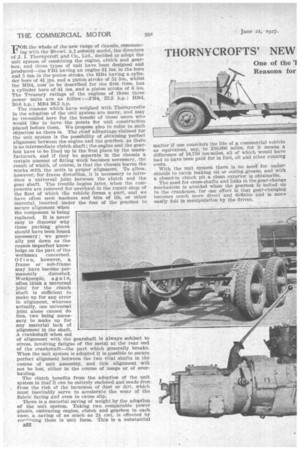
w Chassis with the Latest Power Unit. The mbination of Engine, Clutch and Gearbox in Unit Form.
FOR the whole of the new range of chassis, commencing with the 30-cwt. Al subsidy model, the directors of J. I. Thornycroft and Co., Ltd., decided to adopt the unit system of combining the engine, clutch and gearbox, and three types of unit have been designed and produced—the FB4 having an engine 31 ins, in the bore and 5 ins. in the piston stroke, the HB4 having a cylinder bore of 41 ins. and a piston stroke of 5i ins., whilst the MB4, now tobe described for the first time, has a cylinder bore of 4i ins, and a piston stroke of 6 ins, The Treasury ratings of the engines of these three power units are as follow ;—FB4, 22.5 h.p.; 11B4, 30.6 h.p. ; MM 36.2 h.p.
• The reasons which have weighed with Thornycrofts in the adoption of the unit system are many, and may be recounted here for the benefit of those users who would like to have the points for unit construction placed before them. We propose also to refer to such objection as there is. The chief advantage claimed for the unit system is the possibility of obtaining perfect alignment between the engine and the gearbox, as there is no intermediate clutch shaft ; the engine and the gearbox have to be lined up in the first place by the manufacturers, and if they be separate in the chassis a certain amount of fitting workbecomes necessary, the result of which, of course, is that the chassis leaves the works with the units in proper alignment. To allow, however, for frame distortion, it is necessary to introduce a universal joint between the clutch and the gear shaft. The trouble begins later, when the components are removed for overhaul in the repair shop of the fleet of which the vehicle forms a part, and we have often seen -washers and bits of tin, or other material, inserted under the feet of the gearbox to• secure alignment when the component is -being replaced. It is never easy to discover why these packing pieces should have been found necessary ; we generally put down as the reason imperfect knowledge on the part of the workanan concerned. Often, however, a, frame or sub-frame may hare become per
manently distorted. Workpeople, agal n, often think a universal joint for the clutch shaft is sufficient to make up for any error in alignment, whereas actually, one universal joint alone cannot do this, two being necessary to make up for any material lack of alignment in the shaft. A crankshaft when out of alignment with the gearshaft is always subject to stress, involving fatigue of the metal at the rear end of the crankshaft—the part which generally breaks. When the unit system is adopted it is possible to secure perfect alignment between the two vital shafts in the course of unit assembly, and this alignment will not be lost, either in the course of usage or of overhauling.
The clutch benefits from the adoption of the unit system in that it can be entirely enclosed and made free from the risk of the incursion of dust or dirt, which must inevitably serve to accelerate the wear of the fabric facing and even to cause slip.
There is a material saving of weight by the adoption of the unit system. Taking two comparable power plants, embracing engine, clutch and gearbox in each case, a saving of as much as 2i cwt. is effected by corning them in unit form. This is a substantial B32 matter if one considers the life of a commercial vehicle as equivalent, say, to 150,000 miles, for it means a difference of 18,750 ton-miles, all of which would have had to have been paid for in fuel, oil and other running costs. With the unit system there is no need for undershields to catch leaking oil or oozing -grease, and with a closed-in clutch pit a clean exterior, i,s obtainable. The need for cross-shafts and links in the gear-change mechanism is avoided when the gearbok is bolted up. to the crankcase, for one effect is that gear-changing becomes much more direct and definite and is more easily felt in manipulation by the driver.
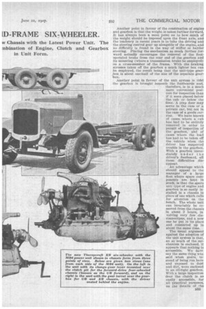
Another point in favour of the combination of engine and gearbox is that the weight is taken farther forward. It has always been a moot point as to how much of the weight should be imposed upon the front axle, and the tendency in recent years is to take the driving and the steering control gear up alongside of the engine, and no difficulty is found in the way of stiffer or harder steering. Placing the mechanism so much farther forward actually encourages the removal of the footoperated brake from the rear end of the gearbox and its mounting (where a transmission brake be employed) on a eross-member of the frame. With the braking stresses taken off the gearbox a much lighter box can be employed, the result being that the unit-type gearbox is about one-half of the size of the separate gear'box.
• Another point in favour of the unit system is tlrat the gearbox is brought beneath the footboards and, therefore, is in a much more convenient position for inspection than if it were placed beloW the cab or below the floor. A trap door may serve in the case of a private car, but not in the case of a goods carrier. We have known of cases where a cab has had to be entirely removed in order to permit of inspection of the gearbox, and e,f cases where the load has had to be taken off the vehicle when the' driver has suspected trouble in the gearbox. With a gearbox immediately under the driver's footboard, all these difficulties disappear.
An advantage which should appeal to the manager of a large fleet where spare components are kept in stock, is that the spare unit type of engine and gearbox is so easily Installed in a chassis in place of one which calls for attention on the bench. The whole unit can invariably be removed from the chassis in about 2 hours, ia. volving very few disconnections, and a new one be put in its place and connected up in about the same time.
The usual argument against the adoption of the unit system is that, as so much of the mechanism is enclosed, it appears that nothing is accessible. We dare say the same thing was said when gears, instead of being run bare and exposed to dust and dirt, were enclosed in an oil-tight gearbox. With a large inspection door the clutch is as easily accessible, for all practical purposes, as the details of the engine and gearbox. With ,a single-plate dry clutch attention is rarely called for. A spanner will undo the half-dozen nuts holding the cover in place, giving immediate access to the adjusting screws for positioning the clutch-operating toggle levers. It is, again, no more difficult to check the timing of the engine, as flywheels are always clearly marked.
It is not always ,possible to argue closely on the question of the position of the gear lever, which, in thecase of the unit, is always in the central position at the driver's left hand. Some people .,have very little use for their left hand or arm, largely because they have not employed it or trained it. In the case of the private motorist he often fears the lever becoming shrouded by the coat of the passenger sitting next to him. On public-service and goods vehicles these objecttons cannot apply, as there is nothing to get in the way or to foul the levers, and in a few weeks even the most useless of left arms can be trained to be of service. There is rather more in the argument that the left arm is more sensitive and delicate in its action and, therefore, is better for steering the vehicle, leaving the right arm tree for brake application. Thornycrofts admit this, and, in the case of their heavier vehicles, whilst placing the gear lever in the centre, they mount the brake lever on the right-hand side of the vehicle.
The different types of engine made by Thornycrofts are allocated as follow :—The BB4 engine is employed
with the J-type 4-tonner and Q-type 5 to 6-tonner chassis; the P134 power unit is employed in the Al, A2 and A2 long, and the A3 six-wheeler chassis; the IIB4 power unit is to be found in the KB 3-tonner, the SB and LB passenger chassis and the PB 4-tonner vehicle with a forward drive. The II1B4 engine-will be employed in three new models, of which one is now to be described. These will be known as the t"B passenger chassis with a low frame, intended for singledeck buses or coaches to seat 28 to 30 passengers, with a gross loud not exceeding 3i tons, and the 1.B. forward drive chassis for the same sort of work, but accommodating a vehicle that will seat 32 passengers. The third Model is the XB rigid six-wheeler, capable of dealing with loads of five tons over the highway or of three tons across country. We propose here to (...scribe the six-wheeler, as this enables us to deal with a chassis of striking features and to go fully into the details of the 31134 Jana.
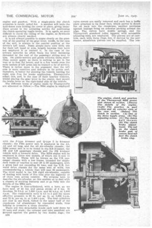
The engine is four-cylinclered, with a bore, as we have said, of 41 ins, and piston stroke of 6 ins. It develops 50 E.h.p. at 1,000 r.p.m. and 00 b.h.p. at 1,800 r.p.m. The compression ratio is 4.1 to 1 and the mean effective pressure is 90 lb. per sq. in. at 1,000 r.p.m. and 72 lb. per sq. in. at 1,400 r.p.m. The four cylinders are cast in one block, bolted to the upper half of the crankcase (of aluminium) by concealed studs, thus helping to preserve a clean exterior.
There are two detachable beads each held down by ii nuts and studs ; the exhaust and inlet manifold are secured against the gasket by two double. dogs ; the
334 valve covers are easily removed and each has a baffle plate attached to its inner face, which serves to direct the oil back into the crankcase, .another provision against leakage being an asbestos packing around the edge. The valves have double springs, and the Thornycroft standard roller tappets, with accessible adjusting nuts, are employed. The pistons are of castiron, each with three rings, but, if desired by the purchaser, aluminium pistons can be supplied. The eon
Water is circulated by a propeller pump, mounted in the intake lead, with an outside adjustment for the packing gland. The pump shaft is driven by a Whittle belt off the magneto shaft and the fan is mounted on a prolongation thereof. The carburetter is a Zenith and interposed between it and the cylinder block is a mounting which carries the governor throttle. The governor consists of three balls in a cage enclosed in a casing at the forward end of the camshaft, 'centrifugal action on the balls causing a coned plate, through a rack, pinion and wire, to affect the position of the governor throttle according to the speed of the crankshaft. The engine of a freight vehicle is governed at 1,900 r.p.m. Usually, for passenger vehicles, whilst the governor is fitted to them it is not connected up to the carburetter; this connection, however, can easily be made if at-anytime it is required. A Simms magneto with a vernier coupling and automatic control of the timing is employed, so that the only control lever on the steering column is that which determines the minimum setting for the throttle.
The power. is transmitted through a single-plate clutch, with a clutch brake, to the gearbox, which gives fonr forward sPeeds and reverse, the gear ratios being as follow:-5.12 to 1, 2.75 to 1, 1.56 to 1 and direct. The reverse gear ratio is 7.68 to 1. The final-drive ratio between worm and worm wheel is 7.25 to 1. At the rear end of the gearbox Is mounted an Auxiliary change-speed gear with a ratio of 2.5 to 1, thus providing a group of low gears when the chassis is
required to be taken over rough country. With the low auxiliary gear in the transmission line, the gear ratios would be 12.8 to 1, 6.87 to 1, 3.9 to 1 and 2.5 to 1, the ratio of the reverse gear then being 19.2 to 1. Thus, it will be seen that on low gear a final ratio between engine and road wheel of 105.6 to 1 can be obtained. A lower gear ratio could, of course, be provided if the alternate of 8.25 to 1 worm and worm wheel were fitted, the makers being prepared to do this.
A small point which calls for mention, typical of the excellence of the design, is the very thorough manner in which the requisite quantity of oil for lubricating the clutch" ball-thrust bearing, the clutch-withdrawal bush and the bearing at the forward end of the clutch 'shaft is provided.
The weight of the unit is 13 cwt. 2 qrs. 18 lb.
A platform is cast on the upper half of the crankcase to carry the magneto and the dynamo in tandem, and should .it be necessary to remove the dynamo for overhauling or adjustment, the magneto can be moved to the forward position and coupled direct to the magneto shaft. Provision is made for an engine starter, the flywheel having teeth already cut for engagement with the starter
pinion. The tyre pump or powertake-off, lx;hen fitted, is bolted direct to the gearbox, the driven pinion meshing with the constant-running wheel ; provision for driving a speed and mileage recorder is made at the rear of the gearbox, except when the auxiliary gearbox is required on a six-wheeler.
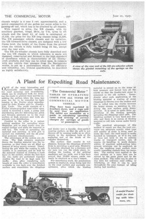
The power is taken through a propeller shaft with an intermediate shaft, the rear end of which is supported in a ball 'bearing attached flexibly to the second Cross-member of the frame. The two driving axle units are standard axles as used on the KB-type chassis, with overhead worm and with a universal joint between the two axles. The suspension of the two rear axles complies with the War Office requirements for rigid six-wheelers, ensuring equal distributien of weight on all four wheels, freedom from spring distortion under all conditions of driving and braking and irrespective of the relative movement of the driving axles. The gimbals to which the rear ends of the springs are coupled are extremely well supported, and there are no torque tubes and no radius rods. Four semi-elliptic inverted springs of ample width (4 ft. 6 ins.) and length are employed, and a difference of 9 ins, in driving axle levels is possible, either axle being able to tilt to an angle of 13 degrees, and each. is cushioned on a rubber block at the top or bottom of the tilt. Disc-type wheels are bolted to the east-steel hubs, which run on roller bearings, and they. are equipped with 38-in. by 7-in. straight-sided pneumatic tyres. The wheelbase of the XB six-wheeler is 12 ft. to the forward axle of the bogie and 14 ft. 3 ins, to the midway position between the two driving axles A long wheelbase, 3 ft. 9 ins. longer than the one mentioned, can be provided. The ground clearance with a 7-in. tyre is 11 ins. The chassis weight is 4 tons 3 cwt. approximately, and a petrol consumption of one gallon per, seven miles is the passing-off test, which haste be attained by all chassis.
With regard to price,, the NB chassis, with its auxiliary gearbox, wings, 38-in., by 7-in. tyres to all wheels and the usual kit of tools is catalogued at £1,150, the price for the NB long chassis being The UB passenger vehicle chassis and its variation, the 1:TB forward-drive chassis, are designed with a low frame level, the height of the frame from the ground when the vehicle is fully loaded being 24 ins., except over the rear axle.
The XB six-wheeler chassis here fully described and the two UB chassis to which reference is made are designed, constructed and finished to the high standard of excellence which is characteristic of all Thornycroft products, and they can be relied upon, in common with any vehicle that emerges from the Basingstoke works, to put up a performance which, for efficiency and reliability, can, without qualification, be described as highly satisfactory.