


A SIX-WHEELER OF REVOLUTIONARY DESIGN.
Page 52
Page 53

Page 54

If you've noticed an error in this article please click here to report it so we can fix it.
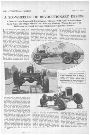
A New 5-7-ton Scammell Rigid-frame Chassis With One Worm-driven Back Axle and Bogie Wheels on Rocking Casings Which Permit 4 ft. Difference in Level Between Diagonally Opposed Wheels.
LAST Friday we were present at a demonstration of an entirely new type of rigid-frame six-wheeled Scammoll chassis which proved conclusively that the latest product of Scanunell Lorries, Ltd., 14, Holborn, London, E.ai, has remarkable potentialities, for it can certainly overcome obstacles which would undoubtedly smash up even a Six-wheeler of the ordinary pattern; in fact, during a W.D. test of this machine the authorities refused to allow one of its own six-wheelers to follow in the path of the newcomer. The chassis is of particular interest in that it is the first rigid-frame type Produced by a company which has developed the articulated six-wheeler to an excellent pitch of perfection and for carrying loads up to 25 tons.
The machine was primarily designed f or overseas work on bad roads or in places where no roads exist, although the principles embodied in its construe tion can just. as well be applied to a chassisfor the transport of passengers or goods on ordinary roads; in fact, it has special advantages for bus work. The, demonstration model is being supplied to the Colon Development Co. for work in the 'oilfields of Venezuela, and in its final form will have a flat platform body with very narrow cab, so that long pipes and derrick members can be allowed to project to each side of the cab, enabling pieces up to 35 ft. in length to be carried. The useful load capacity is from 4 tons toT tons, according to the conditions of service, and the chassis weight is 5 tons.
We will deal first with those parts of the chassis to which it mainly owes its remarkable powers, and these, as might be expected, are the back axle and the driving wheels, and in inspecting them the first thing that strikes the -observer is that only one back axle is employed, and this is carried on 1126 semi-elliptic springs mounted in normal manner, being pinned to frame brackets at the front and carried in slides in frame brackets at the rear, th6 drive to this axle being by overhead worm, although in the bus it is intended to use spiral bevels to permit larger ground clearance with the low-level frame which will be employed and
which we illustrate diagrammatically. Carried on two plain bearings at each end of this axle is a. robust steel casing, to the front and rear ends of which are bolted and keyed aluminium casings carrying live stub axles for the driving wheels. On the outer ends of the diffcrential shafts are spur gears, which mesh at each side with large intermediate pinions, through which the drive is taken to spur gears mounted on the stub axles. The ratio of the
gear is such that the worm gear runs at approximately double its normal speed, but under only half the normal load—ideal conditions for this type of drive The whole of the final drive by spur gearing is thus contained in the rocking casings. It is totally enclosed and runs in an oil-bath, which will require re
plenishing only two or three times .a year, as felt rings, held securely by adjustable clips, are. employed to prevent loss of lubricant at such..points as the sides of the two bearings of each of the rocking casings. These bearings are well separated, arms from the centre portion of each casing extending to the inner bearing: It will readily be understood that• this method of construction provides most unusual flexibility. The rocking
action is only limited by the inwardly extended arms of the rockers coming into contact with the semi-elliptic springs, and the actual allowable lift of any wheel is 2 ft., whilst there is no need for supplementary retaining loops or other devices for restricting wheel movement.
An excellent point is that there is sery little movement of the axle, not even so much as in an ordinary fourwheeled vehicle ; consequently, the driving line is practically straight all the time, and this compares very favourably with the extraordinary angles to which the propeller shaft and intermediate shaft of a two-axled bogie are subjected.
Now we come to another important point in the construction. This is the centrally pivoted cross-spring for the front axle, which allows this member to rise or fall at each side without causing any torsional stresses on the chassis frame. In a vehicle designed for cross-country work, it is essential that the front axle should be able to resist severe concussions in practically the horizontal plane, and no ordinary axle or method of springing is designed to take such shocks; but in the Scammen there extends from the ends of the 4-in, tube, which forms the axle proper, a heavy channel-section member which is taken back in V-form to a ball-andsocket device carried on forwardly projecting arms forming part of an immensely strong cast-steel crossmember of the frame; thus, any stresses which would tend to force the front axle backwards are transmitted direct to the chassis frame.
The result of the whole arrangement of the front and rear suspension is that the frame and body assume the average angle of the four rear wheels, and under the most trying conditions, with the vehicle crossing steep banks at an angle, we could not observe any flexion of the frame.
There is another point in favour of the new design. The driving wheels never leave the ground; even when the vehicle was driven directly over a. vertical bank 2 ft. 4 ins. high the driving wheels kept to the ground as if glued to it, although when this bank was taken at a speed of 8-10 m.p.h: the front wheels of the vehicle lifted clear of the ground to a height of some 5 ft. and dropped to the ground with great violence—a drastic test to which we believe no other maker. would venture to submit his product.
The vehicle under review has a fourspeed gearbox, giving ratios of 11.4 to 1, 20.0 to 1, 30.8 to 1, 59.1 to 1 and reverse 75.8 to 1, but if required a five-speed box can be fitted. This gives a further reduction of 117.7 to 1 with a reverse of the same ratio. The tyre sizes are 44 ins. by 10 ins., so that the actual ratios are higher in proportion to those of a vehicle with wheels of ordinary size. Despite this,
the test of charging a bank to which we have just referred was done on second speed.
• The power unit is identical with that used on the standard Scammell. It is a four-cylintlered monobloc with a bore of 5 ins, and a stroke of 5 ins., the overhead valves being carried in detachable heads and operated by rockers and push rods from a camshaft in the crankcase. The compression is 4i to 1, and the unit develops 55-60 b.h.p. at 1,200 r.p.m. and a maximum of 65 b.h.p. It has aluminium-alloy pistons, Duralumiu connecting rods and a crankshaft of nickel-chrome steel. The magneto has an automatic advance device. The engine is carried in a channel-steel subframe supported at three points.
The drive is transmitted through a standard Scammell Perodo-faced cone clutch to the separately mounted gearbox. A single tubular propeller shaft with Hardy-Spicer joints leads from the gearbox to the rear axle.
Within each driving wheel is a brake drum, and the shoes are expanded by cams operated by levers and rods lying on the top of the rocking casing at a point convenient for adjustment. These rods are in turn connected to short arms on vertical shafts, also carried by the casings. On the lower ends of these shafts are levers connected by short lengths of steel cable to bellcranks carried by the axle casing. This brake linkage. The hand-brake controls the shoes in one pair of opposite wheels, whilst the pedal controls those in the other pair. Since, however, the wheels at each side are positively connected through the trains of spur gears, each brake actually operates on all four wheels.
The Goodyear tyres are rated to carry, up to 21 tons each, making a total rated capacity for the six wheels of 16+ tons ; therefore, with a chassis weight of 5 tons and a gross load of, say, 6 tons, the tyre equipment is still well within the load capacity. This enables the reasonably low inflation pressures to be used, which • assist the vehicle when travelling over soft ground by preventing the wheels from sinking.
In the ordinary six-wheelci, if a hummock be traversed and the lift or fall permitted by the retaining straps be exceeded, the whole of the load on the bogie is brought on to the wheels and the tyres of one axle, the other bogie wheels remaining suspended in the air. Thus, one axle is overloaded to the extent of 100 per cent., whereas in the new Scammell this cannot occur,
although there' may be a slight trans;..,\A•1 NVIZOMMA. ference of the load to the rearmost wheels when the vehicle is climbing, 4 which in the most extreme case, when mounting a gradient of 1 in 2+, would be not more than approximately 1,009 lb., and this is claimed to be rather an advantage than otherwise, for it assists the forward bogie wheels in lifting over obstructions. A point in the design of the five-speed gearbox is that there is no question of a supplementary gearbox. • The box is a unit with four speeds at the front of the bearing and one speed and a reverse behind. This gives a much higher efficiency on first gear than is obtained by taking the drive through two trains of gears. Bail
J328 road wheels and gearing, with the exception of the bearings for the rocking casings. The differential shaft spur pinions have hardened and ground teeth, but the larger pinions are of 60ton steel unhardened.
The following dimensions, etc., will be of interest :—Wheelbase, 15 ft., track, 6 ft. 9 ins.; ground clearance, 1 ft. 8 ins.; platform space, 15 ft. by 7 ft. 6 ins.; ratio of worm gear, 5.4 to I; ratio of spur gearing, 2.1 to 1.
The front-axle radius arms act as a protection for the engine sump, and may later be steel-plated to allow this part of the vehicle to slide in cases where a hump comes between the.front wheels. The main frame is of channel-steel 8 ins. deep. Three of the cross-members are steel tubes 4 ins. in diameter and upswept to clear the propeller shaft. The front and second crossmembers are steel castings of hollowbox section. The system of suspension employed for the driving wheels has the advantage that the rise or fall of any one wheel is in a practically vertical plane, and it does not set up any appre ciable lateral force as is caused in the case of wheels attached to the ends of an axle, where there may be considerable sideways displacement of the spring seats, which is bound to affect the chassis frame. In view of the stresses set up by wheels of such large diameter, the steering box provides a reduction which necessitates four turns of the steering wheel to obtain full lock.
So impressed are we by the design of this chassis that we shall look forward with marked interest to any further developments, such as the construction of passenger or goods chassis embodylug these novel principles.