


An Adjustable Steering Box
Page 64
If you've noticed an error in this article please click here to report it so we can fix it.
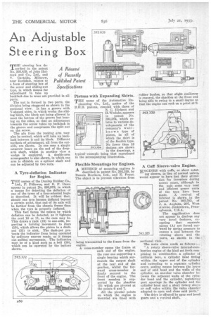
T"steering box described in the patent No. 393,839, of John Eelroyd and Co., Ltd., and V. Gartside, Milnrow, near Rochdale, relates to a form of steering box of the screw and sliding-nut type, in which means for adjustment to take up backlash due to wear are provided in all parts.
The nut is formed in two parts, the division being staggered as shown in the sectional view. It has a groove -with V-shaped sides, in which works the sliding block, the block not being allowed to meet the bottom of the groove but bearing on the sides, so that an adjustment towards the screw takes up backlash in the groove and compresses the split nut on the screw.
The pin from the rocking arm may also be conical, which will take up backlash between it and its block. Different methods of .adjustment, all from the outside, are shown. In one case a simple setterew bears on the end of the droparm shaft, whilst in another view a wedge is employed. A double-arm arrangement is also Shown, in which one arm is slidable on a splined shaft and can be adjusted by two nuts.
A Tyre-deflation Indicator for Bogies.
THE names of the Dunlop Rubber Co., Ltd., F. Fellowes, and R. P. Dawe appear in patent No. 393,572, in which a means for detecting the deflation of one of the tyres of a four-wheeled bogie is described. It will be evident that, should one tyre become deflated beyond a certain point, that end-of its axle will be farther from the chassis frame than when the tyre is properly inflated.
This fact forms the means by which deflation can be detected, as it tightens the cord 10 or 11, as the case may be. This draws a rack (16) to one-side, imparting a turning movement to discs (19), which allows the piston in a dashpot (33) to sink. The dash-pot prevents the indicator from being operated by ordinary uneven roads, as it damps out sudden movements. The indication may be of a kind such as a bell (30), which can be operated by the battery shown.
Pistons with Expanding Skirts.
THE name of the Automotive En gineering Co., Ltd., maker of the B.H.B. pistons, coupled with those of S. C. Hickson and H. Weslake, appears in patent No. 393,584, which relates to various developments of the company's wellknown type of piston, in all of which the skirt is of the flexible type. No fewer than 18 designs, are shown in the drawings, a typical example being that reproduced in the accompanying illustration.
Flexible Mountings for Engines. A METHOD of mounting engines is described in patent No. 393,339, by Dennis Brothers, Ltd., and E. Poppe. The object is to prevent vibration from
being transmitted to the frame from the engine.
A cross-member spans the frame at each end of the engine, the rear one supporting a single bearing which surrounds the output shaft at the rear, end of the gearbox, whilst the forward cross-member is firmly secured to the front of the engine. The front membe,e is supported by the shackles (5) which are pivoted at the points 6 and 7.
All the pivotal points on which the engine is mounted are lined with rubber bushes, so that slight resiliency is ensured, the shackles at the front end being able to swing to a small degree so that the engine can rock on a point at 9.
• A Cuff Sleeve-valve Engine.
ENGINES with cuffs, or short rotat
ing sleeves, inlieu of normal valves, would appear to have lost their attrac
tion for inventors daring recent years, although in the past some very neat and efficient power units of the type have been made. A revival of interest is shown in the patent No. 393,585, of J. A. Anglada, 207, West Avenue, Jenkintown, Pennsylvania, U.S.A.
The specification does not appear to disclose any very novel features, excepting that separate pieces (A) are forced outward by spring pressure to ensure a seal between the rotating sleeve and the ports, as shown in the sectional view.
The main claim reads as follows :— " A rotary sleeve-valve internal-combustion engine of the kind set forth comprising in combination a cylinder of uniform bore, a cylinder head fitting within the upper. end .of the cylinder and extending to a separate cylinder cover, sealing means between the lower end of said head and the walls of. the cylinder, an annular valve chamber between the adjacent walls of the cylinder head and the cylinder,' registering port openings in the cylinder and the cylinder head and a short rotary sleeYe or cuff valve within the valve chamber adapted to open and close said ports."
The drive is, effected by spur and bevel gears and a vertical shaft.