


A New Agricultural Motor.
Page 12

Page 13
If you've noticed an error in this article please click here to report it so we can fix it.
The forthcoming trials of agricultural motors, promoted by the Royal Agricultural Society of England, are attracting a large amount of attention from engineers as well as from agricultural men, and more than one verypractical design has been evolved by engineers for competition, but it is a matter for regret that, although entered for the trials, one of the machines, the Ideal, will not be able to take part in them; manufacturing difficulties have arisen, and the machine will not be completed in time. The invention to which we refer is that of Mr. Frank M. Waller, and it is being .exploited by the Ideal Agricultural Motor Co., Ltd., which company's registered office is at 96, Cheapside, E.C. By the courtesy of Mr. Waller, we are able to reproduce three diagrams which show the general principles on which the motor is constructed, and from these views our readers may see that. the machine is in reality a self-contained implement for ploughing and grass cutting, for use as a portable power plant, or as a tractor for hauling other agricultural implements or wagons.
Such a machine, if well built and made of good materials, and if offered at a reasonable price, should meet. with instant success. From personal experience with all makes of agricultural motors, and from data at our command, we know that, with a 20 hp. motor, the cost for ploughing reed not exceed 4s. 6d. per acre, and cultivating should not cost more than 3s. per acre, whilst for grass cutting, and the operation of reaper and binder, the cost need not exceed is. 6d. per acre. These figures are considerably less than for horse-drawn implements.
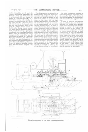
Mr. Waller has aimed at the combination, in one machine, of a motor and the main implements used by farmers for the cultivation of the land, and he appears to have effected the combination without undue complication of design or multiplicity of parts. The engine may be of any sturdy make capable of developing 2i) b.h.p., and the power is first transmitted through a clutch and a simple two-speed-and-reverse gear to a layshaft (A). On this shaft a differential gear (not shown in the diagram) may be mounted at B, and when so fitted the planetary pinions would mesh with bevel wheels that are secured to extensions from the bevel pinions (C and D), which latter pinions mesh with the bevel wheels (E and F) on two short transverse shafts; on the ends of these shafts the final-drive pinions (G) are mounted.
For all ordinary running on the road the differential gear would remain in operation, but, for employment on land for ploughing, etc., for which purpose it is absolutely necessary that the machine should be capable of being turned practically about on one of its own hind wheels, just as a horse-drawn vehicle, and to enable the machine to be mameuvred in a narrow headland, Mr. Waller has resorted to an ingenious yet simple arrangement, which permits the differential gear's being rendered inoperative, and then, by either of the pinions (C or D), the whole of the engine's power may be transmitted to one of the road wheels —the other road wheel remaining stationary and acting as a pivot around which the tractor may be turned. Either or both of the pinions (C and D) may be locked to the layshaft (A) by means of clutches (H and .11 which are actuated, through suitable levers, from a wheel (K) which is mounted below the steering wheel. The steering-chain drum, by the way, is mounted on the fixed back axle, and it is operated by worm and worm wheel in approved traction-engine style.
The frame (L), by which the grasscutter-bar (M) is carried, is pivoted on the horn plates at N, and the cutter is driven from the layshaft (A) through a chain and chain wheel (0) to a short shaft (.1?), and thence, by means of a flexible shaft (k), to a short-throw crank, and, finally, by means of a connecting rod, to a lug on the cutter bar (M). lie chain wheel (0) rides freely on the layshaft (A), and has cast integrally with it one part of a simple friction clutch. A double-ended sliding clutch member (S), which rides on feathers on the layshaft, may be forced by a spring into engagement with the cone on the chain wheel, but it is normally held out of engagement by means of a pin (T) which may be inserted in a quadrant below the hand lever (V). The chain wheel (0) may also be employed for the driving of the reaping-and-binding gear of a standard binder, which machine, by means of suitable traction bars, may be hauled alongside the tractor.
The plough shares are secured to a frame which is slung from three interconnected bell-crank levers (U). It is obvious that, with the wheels on one side of the tractor in a furrow and those on the other side on high ground, some means of adjustment tor the level of the ploughs is necessary, or the various shares will turn over varying depths of earth; in order to correct that obvious disadvantage, one side of the plough frame may be raised or lowered by means of a hand-operated screw and nut (W). The plough frame may be pulled up clear of the earth by means of a small engine-driven winch (X) which may be brought into operation by pulling up the lever (V) so este force one end of the sliding cone (S) into engagement with a corresponding cone on the winch. When the plough frame is raised to its highest point, the cone clutch will slip. A pawl and ratchet is provided to hold up the plough frame so long as is required.
For puller transmission purposes, a. removable pulley (Y) is provided, and, of course, the belt may be driven at two different speeds in one direction, and one speed in the opposite direction.
In order to obtain a good tractive grip on soft land, the rear wheels are provided with paddles which automatically clear themselves from accumulations of earth. A reciprocating motion is given to the paddles by means of a face cam (Z); this cam may be rotated about the axle so that, when working on land, the maximum projection of the pedals from the rim of the wheel occurs at the lowest point of rotation, or, if the earn be moved through an angle of 180 degrees, the paddles remain flush with the tire on tho ground line, but project to their maximum extent at the highest point of tho wheel. These paddles may. quickly be removed when the machine. is to be operated on hard roads.