


A Gas Turbine for Road Vehicles
Page 64
If you've noticed an error in this article please click here to report it so we can fix it.
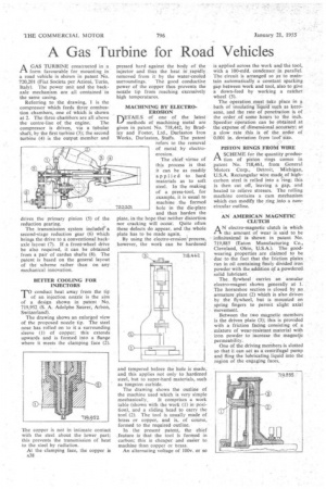
AGAS TURBINE constructed in a form favourable for mounting in a road vehicle is shown in patent No. 720,201 (Fiat Societa per Azioni, Turin, Italy). The power unit and the backaxle mechanism are all contained in the same casing.
Referring to the drawing, 1 is the compressor which feeds three combustion chambers, one of which is shown at 2. The three chambers are all above the centre-line of the engine. The compressor is driven, via a tubular shaft, by the first turbine (3); the second turbine (4) is the output member and drives the primary pinion (5) of the reduction gearing. The transmission system includes° a second-stage reduction gear (6) which brings the drive to a conventional backaxle layout (7). If a front-wheel drive be also required, it can be obtained from a pair of cardan shafts (8). The patent is based on the general layout of the scheme rather than on any mechanical innovation.
BETTER COOLING FOR INJECTORS MO conduct heat away from the tip I of an injection nozzle is the aim of a design shown in patent No. 719,952 (S. A. Adolphe Saurer, Arbon, Switzerland).
The drawing shows an enlarged view of the proposed nozzle tip. The steel nose has rolled on to it a surrounding sleeve (1) of copper; this extends upwards and is formed into a flange where it meets the clamping face (2).
The copper is not in intimate contact with the steel about the lower part; this prevents the transmission of heat to the steel by radiation.
At the clamping face, the copper is x38
pressed hard against the body of the injector and thus the heat is. rapidly removed from it by the water-cooled
surroundings. The good conductive power of the copper thus prevents the nozzle tip from reaching excessively high temperatures.
MACHINING BY ELECTROEROSION DETAILS of one' of the latest methods of machining metal are given in patent No. 718,442, by Bradley and Foster, Ltd., Darlaston Iron Works, Darlaston, Staffs. The patent refers to the removal of metal by electroerosion.
The chief virtue of this process is that it can be as readily applied to hard materials as to soft steel. In the making of a press-tool, for example, it is usual to machine the formed 72q201 hole in the die-plate
and then harden the plate, in the hope that neither distortion nor cracking will occur. Quite often these defects do appear, and the whole plate has to be made again.
By using the electimerosion process, however, the work can be hardened and tempered before the hole is made, and this applies not only to hardened steel, but to super-hard materials, such as tungsten carbide.
The drawing shows the outline of the machine used which is very simple mechanically. It comprises a work table (shown with the work (1) in position), and a sliding head to carry the tool (2). The tool is usually made of brass or copper, and is, of course, formed to the required outline.
In the present patent, the chief feature is that the tool is formed in carbon; this is cheaper, and easier to machine than copper or brass.
An alternating voltage of 100v. or so is applied across the work and the tool, with a 100-mfd. condenser in parallel. The circuit is arranged so as to maintain automatically a constant sparking gap between work and tool, also to give a down-feed by working a ratchet wheel (3).
The operation must take place in bath of insulating liquid such as kerosene, and the rate of penetration is of the order of some hours to the inch. Speedier Operation can be obtained at the expense of dimensional accuracy; at a slow rate this is of the order of 0.001 in. deviation from toot size.
PISTON RINGS FROM WIRE
ASCHEME for the quantity produclion of piston rings comes in patent No. 718,461, from General Motors Corp., Detroit, Michigan, U.S.A. Rectangular wire made, of highcarbon steel is rolled into a -ring; this is then cut off, leaving a gap, and heated to relieve stresses. The rolling machine contains a cam mechanism which can modify the ring into a noncircular outline.
AN AMERICAN MAGNETIC CLUTCH
AN electro-magnetic clutch in which the amount of wear is said to be infinitesimal is shown in patent No. 719,885 (Eaton Manufacturing Co., Cleveland, Ohio, U.S.A.). The goodwearing properties are claimed to be due to the fact that the friction plates run in oil containing finely divided iron powder with the addition of a powdered solid lubricant.
The flywheel carries an annular dectro-magnet shown generally at 1. The horseshoe section is closed by an armature plate (2) which is also driven by the flywheel, but is mounted on spring fingers to permit slight axial movement.
Between the two magnetic members is the driven plate (3); this is provided with a friction facing consisting of a mixture of wear-resistant material with iron powder to increase the magnetic permeability.
One of the driving members is slotted so that it can act as a centrifugal pump and fling the lubricating liquid into the region of the engaging faces,