


Patents Completed.
Page 20
If you've noticed an error in this article please click here to report it so we can fix it.
Complete specifications of the following patents will be sent to any address in the United Kingdom up receipt of eightpence per copy at Sales Branch, Patent Office, Holborn, W.C.
TIRES.—Mulie.—No. 13,532, dated 25th June, 1908.—This invention relates to tires of the type in which halls are placed within the inner space of the tire and embedded in a jelly-like filling. A number of solid, elastic, rubber balls is placed in the tire, the balls preferably being coated with an adhesive substance so that they will adhere together, and the whole of the internal space of the tire can be filled uniformly with balls. The tire is then placed on the rim, and is pressed against the fixed flange of the latter The loose flange is then fixed in position in the usual manner. A fluid substance consisting of a mixture of glue, gelatine, glycerine, mercury chloride, zinc and sulphur is then pumped through a hole into the tire, thus filling up the space between the balls. When the substance becomes solidified it forms, with the balls, a very resilient filling for the tire.
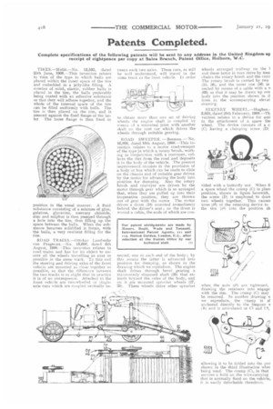
ROAD TRAINS.—Ottokar Landwehr von Pragenau.—No. 18,608, dated 6th August, 1908.--This invention relates to road trains and has for its object to ensure all the wheels travelling as near AS
• possible in the same track. To this end the steering and driving axles of the front vehicle are mounted as close together as possible, so that the difference between the two tracks is so slight that in practice it is of no consequence. Attached to the front vehicle are two-wheeled or single_ axle cars which are coupled centrally be
tween each two axles. These cars, as will be well understood, will travel in the same track as the front vehicle. In order
to obtain more than one set of driving wheels the engine shaft is coupled by means of a universal joint with another shaft on the next car which drives the wheels through suitable gearing.
ROAD SWEEPER. —Beeman. —No. 16,808, dated 10th August, 1908.---This invention relates to a motor road-sweeper of the type in which a rotary brush, working in conjunction with a conveyer, collects the dirt from the road and deposits it in the body of the vehicle. The present improvement consists in the provision of a body or box which can he made to slide on the chassis and of suitable gear driven by the motor for advancing the body into position for dumping. Also the rotary brush and conveyer are driven by the motor through gear which is so arranged that, when they are pulled up into their inoperative position, they are thrown out of gear with the motor. The motor drives a drum )18) mounted immediately behind the driver's seat ; on the drum is wound a cable, the ends of which are con fleeted, one to each end of the body ; by this ineans the latter is advanced into position for dumping, as shown in the drawing which we reproduce. The engine shaft drives through bevel gearing a transversely disposed shaft (26) that extends beyond the sides of the body, and on it are mounted sprocket wheels (27, 28). 'Fhese wheels drive other sprocket
wheels arranged midway on the 1 and these latter in turn drive by mea chains the rotary brush and the cony The rotary brash is carried by two (55, 56), and the outer one (56) is nected by means of a cable with a v (66) so that it may be drawn up ove body into the position shown in d lines in the accompanying elevat drawing.
STEPNEY WIIEEI..—Hughes.3,825, dated 20th February, 1808.—Th vention relates to a device for assi in the attachment of a spare Ste wheel. The device consists of a c (C) having a clamping screw (D) vided with a butterfly nut When fi a spare wheel the cramp (C) is plac( position, shown in figure herewith, the screw (D) is employed to draw two wheels together. This causes nose (62) of the retaining device to the tire (al-) into the position sb when the nuts (1,3) are tightened, drawing the retainers into engage with the rim. The cramp (CI may be removed. In another drawing sc we reproduce, the cramp is sI anchored directly to the Stepney v (111 and is articulated at Cl and C2,
allowing it to be folded into the pos shovim in the third illustration whey being used. The cramp (C), in that secures a hold on the wire-carrying that is normally fixed on the vehicle, it is easily detachable therefrom.