


The Renard Road Train Demonstration.
Page 6
Page 7
If you've noticed an error in this article please click here to report it so we can fix it.
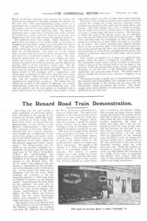
On Friday last, the r5th instant, a large gathering of interested gentlemen assembled at the garage of the London and District Motor Bus Company, Limited, at Farm Lane, WaIham Green, S.W., to witness the first demonstration, in this country, of the Renard " self-propelling " road train. The evolutions ot the train, both in a forward and in a reverse direction, were carried out, satisfactorily, in the yard of the garage, and quite a number of the visitors enjoyed a run round the premises on the train, which, for the moment, suggested a novel "roundabout." The demonstration was followed by an excellent luncheon in a temporary structure, and this was presided over by Sir Henry Seton-Karr, C.M.G. The speech-making was limited to the toasts of the King, the President of the French Republic, and success to the Renard train. Mr. H. F. Foster, who replied to the last named, is responsible totthe introduction of the Renard system to this country. In his speech, he made out an admirable case for the train, whilst avoiding any reference to the allimportant question, " Will such trains be allowed to operate on our English roads?" Good progress has been made by the syndicate : the train only arrived in this country, we understand, within two days of the display, and, already, representatives of the India Office, the War Office, the Colonial Office, and the Local Government Board, had inspected it. War-Office trials took place on Tuesday lase
The manufacture of the Renard train in this country is to be undertaken by the Daimler Company, at Coventry, and both Mr. Edward Manville and
Mr. Percy :+lartin were interested spectators on Friday last. The useful load capacity of this train can reach a maximum. of 20 tons, and this work was contrasted, by Mr. Douglas Story, with the carriage of goods by donkey peswer, abroad : 240 of these animals, forming a string i mile long, were required to transport a weight of 15 tons.
The total tare weight of the Renard train, as shown, is to tons, 16 cwt. : it is propelled by a four-cylinder engine, rated at 75h.p. The cylinders are cast in pairs, and bolted down to the crank-chamber, which is a single casting in aluminium. The engine is the product of J. Filtz, I.evallois (Seine), and is a substantial piece of mechanism. The tractor, or powerwagon, has a tare weight of 3 tons, 2 cwt., and it is stated that the maximum load on each axle is I ton, 15 cwt. The warning whistle is a neat device, and is worked by the exhaust, which, after leaving the large silencer, placed outside the frame of the tractor, on the near side, is led, by a vertical pipe, to a point above the level of the roofs of the coaches comprising the train. A driver, his mate, and a boy are employed to work tire train on the road, and the necessity for this staff is evident when a reverse motion is being given to the coaches. In this case, after an adjustment of the steering gear, the driver's mate, by means of a steering handle fixed, temporarily, to the free connections at the rear of the hindmost carriage, pilots the train from that end. While the engineer is occupied in giving movement to the whole, the boy devotes his attention to the middle of the train, to safeguard that portion from contact with any wall, or other obstacle, about which the vehicles are being manceuvred. The system is interesting, because it differs from others, inasmuch as the central wheels of each" trailing "vehicle are driven, by means of universal joints, and shafts, from the engine on rhe power unit. This power unit is not intended to accommodate any freight. The load is carried upon the "trailing" vehicles, which, obv:ously, can be taken to their destination, and left there, while the tractor can run to another point to pick up a new load, or an empty " trailer " : in this way, useful work can, always, be accomplished, and without waste of time. When designing the " train," the inventor had, of necessity, to keep three.. important points before him. These were : the drive from the power unit to each "trailer" had to give equal efficiency on gradients, and curves, as upon the level ; each " trailing vehicle must track, correctly, with the one immediately in front of it ; and, lastly, that some form of compensated suspension would be required.
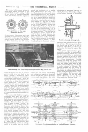
The success with which the foregoing difficulties have been met may be judged from a study of the diagrams ; these show the two sectional elevations and a plan, of the Renard "trailing " vehicles. The drive from the power unit is taken, in each " trailer," by short shafts (1, 2, 3, 4, and 5) which are furnished with universal joints. Reference to the figures shows that the member (2) drives a differeatial shaft 12), pieced between the first and second pairs of wheels, in the forward direction in which the vehicle, normally, runs. The transmission from the ends of the differential shafts is by side chains (15), running over sprockets (13 and 16) To obviate the slipping of the wheels, which would take place when
" train " of, say, four vehicles, was being steered from a curve of a large radius to a smaller one, the central
wheels are furnished with a spring drive, which obviates this defect. Our two illustrations show the details of the the compensating device, and the manner in which the action is effected. A box (a) is integral with the sleeve (b), and this portion carries two pieces (d), which form a bearing for one end of a spiral spring (c). The box is covered in by a plate (g), and this plate forms part of the large sprocket to carry one of the driving chains. A dog (1) projects inwards from the face of the cover (g), and is so disposed that it can lie between the bearing pieces (d); this is its normal position. The other end of the spring (c) presses against f, and tends to force it back between the pieces (d), and, when the vehicle moves from a larger to a smaller circle, the dog (f) tends to compress the spring (c).
The " trailing " vehicles, as menConed earlier, are furnished with six
wheels; the end wheels, both leading and trailing, are ,capable of deflection from a straight line, whilst the centre wheels propel the vehicle. The total axle-weig-ht is distributed over the six wheels, by means of levers (30 and 31), which connect the ends of the central
springs to the inner extremities of the end springs. This arrangement allows the central axle to rise, or to fall, in opposition to the others, and the weight is, thereby, distributed in correct proportion.
This system appears to have great possibilities, not only for public-service vehicles in country districts, but, also, for the transportation of agricultural produce, especially in the case of goods which will not stand excessive vibration without depreciation. Practical running tests show that, owing to the suspension upon six wheels, the movement over rough roads, such as field tracks, is remarkably easy, and there is a marked absence of side-slip. For military purposes, too, the utility of this system is beyond doubt, as it is independent of ordinary roads, and the tractor can be driven by either a petrol or steam engine. The promoters will require, however, to get the Law altered before they can use the machines under the Motorcar Acts.