


Road-sweeper with Kerb-following — Gutter Brush
Page 36
If you've noticed an error in this article please click here to report it so we can fix it.
A Resume' of Patent Specifications That Have Recently Been Published
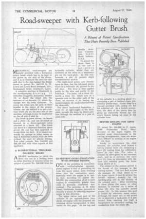
AECHANICAL road-sweepers are IViusually provided with a horizontal rotary brush which has to be kept to the gutter by the skill of the -driver, and it is to eliminate the need for this skill that is the idea behind the design shown in patent No. 546,123 by W. Lewin and Lewin Road Sweepers, Ltd., Shakespeare Street, Southport, Lancs.
A complete machine is illustrated in the accompanying dr a win g. I t embodies staggered horizontal brushes (2) to direct the refuse into the entrance of an elevator (1) which discharges into the body container. To sweep the refuse into the path of these brushes is the object of the present scheme, and the method is to use a vertical brush (3) on the near side of the machine, although it may be duplicated on the off side if need be.
The brush is power driven, via bevels and a chain (4), and can be raised or lowered by a driver-operated cable attached to a beam (6). The brush can move in a sideways direction about pivots (5) and tan thus approach or recede from the kerb. It is biased outwardly by, springs or other means so that it maintains contact•with the .kerb without the need for precise driving. Two other patents, Nos, 545,058 and 545,120 deal with other aspects of this appliance.
A BI-DIRECTIONAL TWO-LEADING-SHOE BRAKE ABRAKE mechanism in which the shoes can act in a leading sense in either direction of rotation forms the subject of patent No. 546,036 from the
Bendix Aviation Corporation, South Bend, Indiana, U.S.A.
To spread the shoes there is at one end a two piston hydraulic cylinder, whilst they are anchored at the other to a stationary pin on the back-plate. At this end, however,, a slot (3) permits slight circumferential motion.
The right-hand piston acts directly upon its shoe, but the left-hand piston bears on a bellcrank (6) pivoted to the left shoe. The force is thus applied partly to the shoe and partly to the bellcrank. The latter, via a strut (5), moves a lever (4), which acts as a spreader cam to the other ends of the shoes, on account of its having upturned tongues (2) sandwiched between the shoe-ends..
For direct *mechanical tperation, a lever (1) at right-angles to the backplate, spreads the shoes by direct pressure through the medium of a pair of push-rods.
TO PREVENT OVER-LUBRICATION WITH OPPOSED PISTONS
ONE of the problems in connection with vertical-cylinder opposedpiston engines is that of preventing oil from the upper piston from draining down into the combustion space, especially when the engine is at rest. In fact, according to patent No. 545,883, the consumption of oil in such engines is considerably greater than what is generally considered economical. The patentee, A. B. Atlas Diesel, Stocikholm, Sweden, proceeds to describe a means for effecting improve meEnts in this direction. .
The upper piston and part of the cylinder of an opposed-piston twostroke oil engine with the proposed oilretaining device incorporated, is illustrated on this page. At the top end
of the cylinder is a packing gland (1) containing a pair of resilient rings, presumably piston-rings. Under these is a channel provided with outletis (3) for the collected oil. As a further precaution, the skirt of the piston may be given an outwardly turned lip (2) which airects falling oil clear of the cylinder bore.
BETTER COOLING FOR ASPIN ENGINE IN patent No. 545,669 by F. Aspin, 1149, Walinersley Road, Bury, inventor of the Aspin engine, are detailed some improvements in the cooling arrangements;. these are somewhat difficult to arrange in an engine " of this type. " • Briefly to recapitulate the chief features, the cylinder head houses a hollow conical valve (7) containing a :port (1) leading from the cohibustion space to the side. The valve is rotated by skew-gears On an overhead shaft, and as it revolves, the valve port (1) lines up alternately with the inlet and exhaust ports, the latter being shown at 2.
The subject of the present patent is the layout of the passages in the cooling system. The cool fluid arrives via passages (6) which direct it to the upper spaces (3 and 8) around the hottest regions, namely, by the sparking-plug and in the vicinity of
the exhaust port. After circulating in these places the water, or other medium, is directed via a series of holes (5) into the cylinder jacket proper (4). In this manner this part
is cooled by relatively warm water.•Although the upper end of the jacket (9) is relatively a backwater, it is prevented from reaching too high a temperature by secondary cooliag, by conduction from the inlets (6).