


IMPROVED CONTROLS FOR THE PEERLESS.
Page 19
Page 20
If you've noticed an error in this article please click here to report it so we can fix it.
Notes on Simple Modifications Which Will Add Greatly to the Comfort of the Driver and Safety on the Road.
WHOSE who use or have the control of Peerless lorries will no doubt agree with the writer that there is plenty of room for improvement in the control gear. With this end in view the following ideas were carried out, the result being successful in every way.
Perhaps the weakest part is the foot accelerator ; this has a very short leverage, and when it becomes slightly worn it is practically impossible to get a smooth acceleration of the engine) as it either refuses to budge with a slight pressure, or else opens the throttle fuel and promptly chokes the engine.
Possibly, with the original pattern Peerless carburetter, these peculiarities were not so pronounced, but, with certain other types which are often used on these lorries, the defects pointed out above are very noticeable.
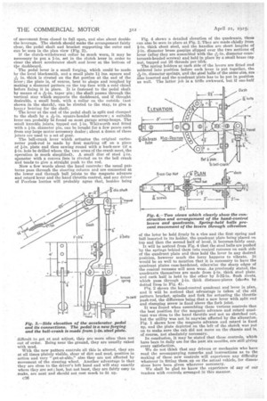
The new pattern pedal gear is shown in side elevation in Fig. 3, and it will clearly be seen that the action is much more sensitive than the old form of gear, because there is 1/ of movement from closed to full open, and also about double the leverage. The sketch should make the arrangement fairly clear, the pedal shaft and bracket supporting the outer end can be seen in the plan view (Fig. 2). If the clutch-withdrawal collar be much worn, it may be necessary to put a 1-in. set in the clutch lever in order to clear the short accelerator shaft and lever at the bottom of the dashboard.
The pedal lever is a small forging, which could be made by the local blacksmith, and a small plate 1i ins, square and in. thick is riveted on the flat portion at the end of the lever; the plate is, of course, bent to shape and roughed by making a diamond pattern on the top face with a cold chisel before fixing it in place. It is fastened to the pedal shaft
by means of a taper pin ; the shaft passes through the vertical stay which supports the dashboard, and if thought desirable, a small bush, with a collar on the outside (not shown in the sketch), can be riveted to the stay, to give a longsr bearing for the shaft.
The lever at the end of the pedal shaft is split and clamped to the shaft by a square-headed setscrew ; a suitable lever can probably be found on most garage scrap-heaps. The small knuckle joints, tapped out I-in. Whitworth and fitted with a t-in. diameter pin, can be bought for a few pence each from any large motor accessory dealer ; about a dozen of these joints are used to a set of gear.
The bell-crank lever which actuates the original carburetter push-rod is made by first marking off on a piece of fin. plate and then sawing round with a hack-saw (if a fin, hole be drilled where the two arms of the crank meet, the operation is much simplified). A small disc of steel fin. niameter with a convex face is riveted on to the bell crank and tends to give a straight push to the rod.
Now a few words about the hand controls: the usual patterns pass through the steering column and are connected at the lower end through ball joints to the magneto advance and retard lever and the hand throttle control, and any driver of Peerless lorries will probably agree that, besides being difficult to get at and adjust, they are more often than not out of order. Being near the ground, they are usually caked -with mud.
With the new pattern controls all this is altered, they are at all times plainly visible, clear of dirt and mud, positive in action and very get-at-able,” also they are not affected by movement of the steering wheel. Another advantage is that they are close to the driver's left hand and will stay exactly where they are set; last, but not least, they are fairly easy to make, are neat and should not cost much to fit up.
c36 Fig. 4 shows• a detailed elevation of the quadrants, these can also be seen in place at Fig. 2. They are made chiefly from fin. thick sheet steel, and the handles are short lengths of t-in. diameter brass gaspipe slipped over the two sections ot 0 lever (after they are assembled with the -in diameter coua1. tersunk-headed screws) and held in place ivy a small brass cap nut, tapped out 26 threads per ifich.
The spring holders at each side of the levers are fitted and soldered into position before each lever is put together, the 72,-in. diameter springs, and the steel balls of the same size, are also inserted and the quadrant plate has to be put in position as well. The latter job is a trifle awkward, but if one-half
of the leer be held firmly In a vice and the first spring and ball inserted in its holder, the quadrant plate being placed on top and then the second half of level., it becomes fairly easy.
It will be noticed from Fig. 4 that the steel balls are pushed by the springs behind them into conical recesses on each side of the quadrant plate and thus hold the lever in any desired position, however much the lorry happens to vibrate. It would be as well to mention that it is necessary to have the quadrant plates case-hardened, otherwise the sharp edges of the conical recesses will soon wear. As previously stated, the quadrants themselves are made from 1-in. thick steel plate. and each half is held to the other by 5-32-in, flush rivets, which pass through t-in. thick distance-pieces (shown by dotted lines in Fig. 4).
Fig. 2 shows the hand-control quadrant and lever in plan, and it will be noticed that advantage is taken of the old pattern bracket, spindle and fork for actuating the throttle push-rod, the difference being that a new lever with split end and clamping screw is fixed above the fork joint.
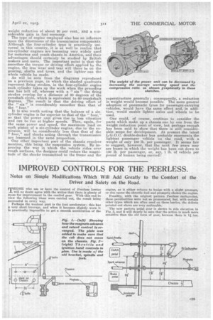
It was found when assembling these various controls that the best position for the magneto advance and retard quadrant was close to the hand throttle and not as sketched out, but the utility was not in anywise affected by the alteration. Fig. 1 shows how the magneto advance and retard is fixed up, and the plate depicted on the left of the sketch was put on to make sure the cab did not move on the chassis and is, of course, not absolutely necessary.
In conclusion, it may be stated that these controls, which have been in daily use for the past six months, are still giving every satisfaction. We do not think that any drivers or mechanics who have read the accompanying remarks and instructions as to the making of these new controls will experience any difficulty whatever in fitting them up on the actual vehicle, for dimensions have been given wherever necessary. We shall he glad to know the experience of any of our readers with controls arranged in this manner.