


Ensuring Even Mixture Distribution
Page 48
If you've noticed an error in this article please click here to report it so we can fix it.
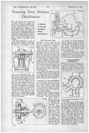
IT is well known that although the 1 several cylinders of an engine may be fed from a common induction pipe, it by no means follows that each induces the same quantity of mixture. Unsuspected eddies, local roughnesses and other hidden factors, may combine to make the power output per cylinder far from uniform. An interesting attempt to remedy this state of affairs is shown in patent No. 577,698, by Morris Motors, Ltd., T. Brown and W. Thomas, all of Engines Branch, Courthouse Green, Coventry.
The method adopted is to supply an excess amount of mixture to each cylinder and then to dispose of the surplus by blowing it out through a pre-set
valve of the safety-valve type. The ejected mixture is fed back to the induction system so that no waste occurs. The drawing shows the scheme in its essentials. Each cylinder is fitted with a pressure-relief valve (1), which can lift against springs and dispose of the excess mixture by way of pipe 2. To prevent the combustion pressure from similarly escaping, a camshaft (3) is employed; this holds the relief valve firmly in the closed position during the power stroke.
By the use of this system, the compressions of a multi-cylindered engine can be closely matched, thus affording improvements in volumetric efficiency and fuel consumption.
• TWO VALVES IN ONE AVALVE layout in which the inlet valve is concentrically disposed inside the exhaust valve is disclosed in patent No. 577,740, by S. Smith, 4, Ballard Estate, New Swanage, Dorset.
The duplex valve is located in the cylinder head and is operated by an overhead camshaft having three cams. The middle one works the inlet valve and the two outer ones the exhaust. The central one is the inlet, and is generally of normal form. The exhaust valve is a hollow member, having an inner seating for the inlet valve and an outer seating of its own. The exhaust pipe is connected with an annular belt (1), whilst the incoming mixture enters pipe 2 and flows over the camshaft. Hairpin-type return springs are used on both valves; only their ends are shown resting in the grooved collar (3).
The essence of the patent lies in the mounting of the main valve guide; this is provided with a spherical seating (4) at its upper end, so as to permit a limited amount of self-centring movement to the valve unit as a whole.
A NOVELTY IN CLUTCH DESIGN AN unorthodox design of clutch is shown in patent No. 577,636, which comes from T, Fawick, Akron, Ohio, U.S.A. This inventor discloses a scheme in which the friction facings are pressed into working contact by the deformation of rubber members.
Referring to the drawing, the flywheel is recessed to form a cylindrical rubbing surface into which the friction material is expanded. The friction surface is built up from 12 separate pieces each mounted upon a segmental shoe (1). The shoes are vulcanized to a pair of rubber rings (2), and these are, in turn, bonded to a pair of metal discs, t h e hubs (3) of which can approach or recede, one sliding on splines. A spring between the two hubs tends to separate them and keep the clutch in the free position.
In operation, the thrust mechanism, which, in this ease, consists of a pair of hydraulic cylinders (4), forces the two hubs together, compressing the rubber rings so that they attempt to increase their diameter. This action forces the friction facings into driving conta■-t with the flywheel bore.
A noteworthy feature of the scheme is that all the thrust stresses are selfcontained, and do not load the whole mechanism in an endwise direction, as does the conventional type of clutch.
A COOLING SYSTEM THERMOSTAT DATENT No. 577,601 comes from A Ellis, and Gummers, Ltd., Effinghani Brass Works, Rotherham, and shows a design for a thermostat for the cooling system of an engine. The device is of the by-passing type, that is, it can direct the water either to the radiator or back to the jacket.
In the drawing, 1 is the inlet pipe. 2 the exit pipe leading to the radiator, and 3 the by-pass which leads back to the jacket. Both the exits are provided with butterfly valves which are worked in opposition by a heat-responsive strip (4). As shown, the device is in the " hot " position, in which the radiator pipe is fully open and the by-pass closed. The wavy form of the heatresponsive member enables a great length to be housed in a small space, with consequent increase in sensitivity. The anchored end is fixed to a stop (5), which is adjustable and can be manually set from the outside to give any desired working temperature.