


Simple Brake Selfadjusting Device
Page 42
If you've noticed an error in this article please click here to report it so we can fix it.
A Réwmt of Recently Published Patent Specifications
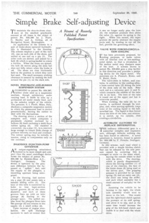
TO maintain the shoe-to-drum clear1 ance at the smallest practicable amount at all times is the object of patent No. 524,180 by J. Pratt, G. Manley and A. Girling, all _ of Navigation Street, Birmingham.
An application of the scheme to a pair of brake-shoes operated hydraulically is illustrated in the drawing. The scheme employs a pair of fiat bars (3), one on each side of the shoes, and united at one end on a pin (1). The other ends are slotted, and joined by a bolt (2) which is spring-loaded to create a friction. When the shoes are pread, the bolt (2) moves along the slots but does not fully return when the brake is off. The, shoes are thus frictionally held in the position in which they were last used. The small necessary working clearance is assured by making the hole around the pin (1) on the slack side.
NOVEL PNEUMATIC-AND-RUBBER SUSPENSION SYSTEM
ACCORDING to patent No. 524,287, rubber alone used as a suspension medium, though satisfactory under varying load, is liable to take up a permanent set under steady load, such as the unladen weight of the vehicle. The patentee, S. I. Pirelli, Milan, Italy, discloses a composite suspension system . in which the permanent load is carried pneumatically, leaving the rubber to deal with the fluctuations.
The drawing shows a section of the complete unit, which comprises a pneumatic chamber enclosed by a bellows (3) itself enclosing a multi-layer
rubber spring (2). The chamber is connected, via a pipe (1), to a reservoir large enough to ensure little change of pressure between no load and overload. The rubber spring. may be initially in tension, rising to compression only on the overload.
INGENIOUS • INJECTION-PUMP GOVERNOR
AN output-regulating attachment, claimed to be more simple aind compact than the usual centrifugal device,
forms the subject of patent No. 524,160 by Daimler-Benz A.G., Stuttgart, Germany. The device is operated by the pressure difference between the by passed or "spilled" fuel, and the supply to the plungers, a throttling aperture being interposed.
In the drawing, fuel arrives via a pipe (2) and passes into a tubular sliding valve .(1). The bore of this tube is connected by holes to four taper-section turned grooves (5) on the outer diameter, and each of these grooves lines up with an inlet passage (6) leading to the plunger space. The spilled surplus from, the plungers flows into.. the passage (3) and returns to the supply via a small orifice (4).
Upon increase of engine revolutions, the spill discharge increases to such an extent that
it can no longer easily pass the bore (4); the resultant pressure then slides the valve (1), against its spring to the
-right. When this occurs, the taper grooves (5) partly obstruct the supply ports and, by tending to cut off the fuel, provide the governing effect.
VALVE WITH FORCED-CIRCULA TION COOLING • IT has been previously proposed, for cooling purposes, to make valves with an internal core of low-meltingpoint metal, so that a circulation of the molten metal may dissipate some of the heat. A scheme shown in patent No. 523,824 goes a step farther in this direction and provides a pumping device for the liquid metal. The patentees are A. Possenti, Rome, and Rietti, Paris.
The valve-stem is hollow, and contains, in addition, to the cooling alloy, a loose central tube (2) fitting the bore of the stern only at the ends, Near each end is a cut-away part (1 and 9) which connects the outside of the tube * (2) to its bore. The bore of the tube is coned out at the upper end but is otherwise parallel.
When working, the tube (2) by its inertia, is oscillated through its endplay, and, when moving upwards, traps some of the cooling liquid in the bellmouthed top. The liquid is then forced down the bore of the tube, and returns, it is staled, up the outside, thus creating a circulation.
AUTOMATIC CLUTCHES TO REPLACE DIFFERENTIAL
THE ordinary differential gear is a somewhat complex_ and expensive unit, although hitherto nothing else has been found so effective. A novel substitute is, however, found in patent No. 524,109 by F. Porsche, Stuttgart, Germany.
In this scheme, each road wheel is provided with a simple friction clutch that can be released by the side pressure caused by cornering; this is arranged to occur en the inner wheel, leaving the outside wheel to deal with the drive. The drawing, which is purely diagrammatic, shows the driving member (1) of one of the clutches, the face of the brake drum (3) being used as the driven part, The gripping pressure is provided by an inner spring (2) and an outer one (4), the inner one being the stiffer, and each wheel assembly has a small amount of end-play on the axle.
Assuming the vehicle to be turning to the right, the whole axle assembly would tend to
move to the left. This would ease the right-hand clutch against the pressure of its stiff spring, and allow it to slip, and at the same time would increase the grip of the left-hand clutch and enable it to deal with the whole drive.