


SOME TIPPING GEARS,
Page 52
If you've noticed an error in this article please click here to report it so we can fix it.
A Resume' of Recently Published Patents.
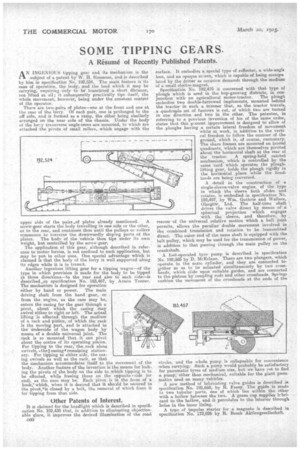
A N INGENIOUS tipping gear and its mechanism is the . subject of a patent by W. II. Simmons, and ia described by him in specification NO. 192;524. The main feature is-its ease of operation, the body, and the load which it may be carrying, requiring -only to be translated a short distance, not lifted at all; it subsequently practically tips itself, the whole movement, however, being under the constant control . of the operator.
Thee are two-,pairs of .plates—one at the front and one at the rear of the lorry. Of each pair, one is prolonged to the off side, and is formed as a ramp, the tither being similarly arranged on the near .side of the chassis. Under the body of the lorry transverse angle-irons are mounted, to which are attached the pivots. of small rollers, which engage with the
upper side of the pairs ..of plates already mentioned. A
screw-gear starts the body travelling to one side or the other, or to the rear, and continues thus until the pulleys or rollers commence to traverse the downwardly sloping parts of the plates. The body of the vehicle then tips under its own
weight, but controlled by the screw-gear. The application of this gear, although described in reference to motor lorries, is not confined to such application, but may he put to other uses.. One special advantage which is claimed is that the body of the lorry is well supported along its edges while it is in transit.
Another ingenious lifting gear for a tipping wagon—of the type in which provision is made for the body to be tipped in three directions—to the rear and also to each side—is clescribed..4in specification No. 183,467, by Armin Tenner. The mechanism is designed for operation either by hand or power. The Main driving shaft from the hand gear, or from the engine, as the case may be, enters the casing for the gear through a pivot, about which the casing may swivel either to right or left. The actual lifting • is effected through the medium of a rack and pinion, of which the rack is the moving part, and is attached to the underside of the wagon body by means of a double universal joint. The reek is so mounted that it can pivot about the centre of its operating pinion. For tipping to the rear,-the.rack alone swivels, s the casing -11 rernaiping stationary. For tipping to either side, the-casing swivels as well as the rack, so that the mechanism accommodates itself -to the movement of the body. -Another feature of the invention is the means for locking the pivots of the body on the side to which tipping is to be effected, while freeing those on the opposite s side (or end), as the case may be. Each pivot is in the form of a hook; which, when it is desired that it should be secured to the pivoyis closed by a bolt, the removal of which frees it for tipping from that side.
Other Patents of Interest.
It is claimed for the headlight which is described in specification No. 192,430 that, in addition to eliminating objectionable glare, it improves the desired illumination of the road C60 surface. It embodies a special type of reflector, a wide-Luigis lens, and an opaque screen, which is capable of being ruanipu kited by the driver as occasion demands through the medium of a small electro-magnet.
Specification No. 192,479 is concerned with that type of plough which is used in the hop-growing districts, in conjunction with an agricultural motor-tractor. The plough embodies two double-furrowed implements, mounted behind the tractor in such a, manner that, as the tractor travels, a quadruple set of furrows is cut, of which two are turned in one direction and two in the other. The patentee, in referring to a previous invention of his of the same order, states that this present improvement is designed to allow of the ploughs having .a certain lateral freedom of movement
• while at work, in addition to the vertical freedom to follow the contour of the ground, which is, of course, customary. The share frames are mounted on latenal quadrants, which are themselves pivoted about the horizontal shaft at the rear of the tractor. A spring-held ratchet mechanism, which is controlled by the same cord which operates the ploughlifting gear, holds the plough rigidly in the horizontal plane while the headlands are being traversed.
A detail in the construction of a single-sleeve-valve engine, of the type in which the sleeve both slides and rotates, is embodied in specification No. 192,497, by Wm. Guthrie and Wallace, Glasgow, Ltd. The half-time shaft drives the valve direct by means of a spherical projection which engages with the sleeve, and therefore, by reason of the universal relative motion which a ball joint permits, allows the peculiar double movement involved in the combined translation and rotation to be transmitted direct. The outer end of the same shaft is equipped with the belt pulley, which may be usecl for the transmission of power, in addition to that passing through the main pulley on the crankshaft. A foot-operated tyre pump is described in specification No. 192,585 by D. McErlane. There are two plungers, which operate in the same cylinder, and they are connected together so as to be actuated simultaneously by two crossheads, which elide upon suitable guides, and Ore connected to the pistons by coupling rods and other crossheads. Springs cushion the movement of the crossheads at the ends of the
stroke, and the whole pump is collapsable for convenience when carrying: Such a pump would probably be satisfactory for pneumatic tyres of medium size, but we have yet to find a pump; other than mechanical, suitable for the giant pneu matics used on many. vehicles. A new method of lubricating valve guides is described is specification No. 192,669, by R. Fazey. The guide is made in two tubular parts, one of which lies within the other with a hollow between the two. A gease cup eupplies lrbricant to the hollow, and it percolates to the interior through holes in the inner lining.
A type of impulse starter for a magneto is described in specification No. 172,026 by R. Bosch Aktiengesellschaft.