


A Heavy-duty Engine Starter T HE aircraft industry Iia s. directed
Page 42
If you've noticed an error in this article please click here to report it so we can fix it.
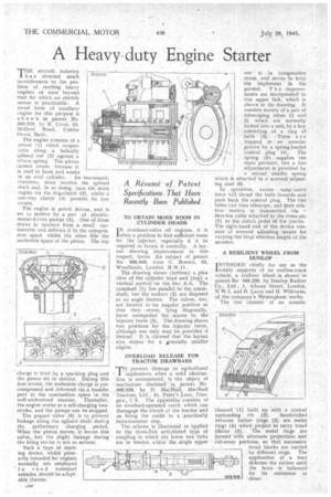
much inventiveness to the problem of starting heavy engines of sixes beyond that for which an electric motor is practicable.A novel form of auxiliary engine for this purpose is shown in patent No 569,020, by R. Cross, 33, Midford Road, Combe Down, Dal h.
The engine consists of a piston (1) which recipromtes along a helically splined rod (2) against a return 'spring,. The piston cannot rotate, because • it is oval form and works in an oval cylinder. Its Movement, .therefore, must revolve the splined shaft and, in so doing, turn the main engine via the deg-clutch (3), whilst a one-way elutch (4) Permits its free return.
The engine is petrol driven, and is set Li motion by a pair of electricmotor-driven pumps (5).. One of these. draws in mixture from a small carburetter and delivers it to the compression space, whilst the other fills the underside space of the piston. The top charge is fired by a sparking plug and the piston set in motion. During this first stroke, the underside charge is precompressed and delivered via a transfer port to the combustion space in the well-understood manner. Thereafter, the engine works as a self-charging twostroke, and the pumps can be stopped.
The poppet valve (6) is to prevent leakage along the sphned shaft duririg the preliminary charging period.. When the piston moves, it leaves this valve,., but the slight leakage during the firing stroke is not so serious.
Such a type of starting device, whilst primarily intended for engines normally not employed ' in road transport vehicles, should be adaptablf thereto.
.1.99 TO OBTAIN MORE ROOM IN CYLINDER HEADS IN overhead-valve oil engines, it is 'often a problem to find sufficient room for the injector, especially if it be required to locate it centrally. .A lay. out showing improvement in this respect, forms the subject of patent No 568,966, from G. Roescb, 53, Woodlands, London, N.W.11.
The drawing shows (bdttom) a plan view of the cylinder head and (top) a vertical section on the linz A-A. The camshaft .(1) lies parallel, to the crankshaft, hut the rockers (2) are disposed at an angle thereto. The valves, too, are located in /an angular position so that their -stems, lying diagonally, leave unimpeded the access to the injector bores (3). The drawing s-hows two positions for the injector bores, although one only may be piovided if desired It is claimed that the layout also makes for a generally smaller erigi ne.
OVER LOAD RELEASE FOR TRACTOR DRAWBARS
-ro prevent damage to agricultural I implements when a solid obstruction is encountered, is the object of mechanism disclosed' in patent No 568,928, by D. ,MacNiell, MacNiell Tractors, Ltd., St. Peter's Lane, Glasgow, C 2. The apparatus consists of an overload-operated catch which can disengage the clutch of the tractor and so bring the outfit to a •practically instantaneous stop.
The, scheme is illustrated as applied to the three-link articulated type of coupling in which the lower two links are in tension whilst the single upper one is in compressiVe . stress, and serves to keep the implement in the ground. T h e improvements are incorporated in this upper link, whieh is shown in the drawing. It consists mainly of a pair of telescoping tubes (1' and 2) which are normally locked into a milk by a key consisting of a ring of balls (3). These a r e trapped in an annular. groove by a spring-loaded conical plug (4). • The spring (5) supplies the main pressure, but a fine adjustment is provided by . • a second smaller spring Which is attached to a screwed adjust ing stud (6). , In operation, excess comp. essiv e force will thrust the balls inwards and push back the conical plug, The two tubes can then telescope, and their relative motion is transmitted via Bowden cable attached to the cross-pin (7) to the clutch pedal of the tractor The right-hand end of the device consists of screwed adjusting meads for varying the total effective length of the member.
A RESILIENT WHEEL FROM DUNLOP I NTENDED chiefly for use as the rotary supports of an endless-track vehicle, a resilient wheel is shown in patent No 569,239, by Dunlop Rubber Co., Ltd., 1, Albany Street, London, N W.1, and B. Lacey and H. Willcocks, of the company's Birmingham works.
The rim consists of an annular channel '(1) built up with a central upstanding rib (2). Sandwiched between tubber rings. (3) are metal rings (4) which project to carry tread blocks (5). The metal rings are formed with alternate projections and cut-away portions. so that Successive tread blocks are carried by different rings. The application of a load deforms the rubber until the force is balanced by its resistance to shear.