


Oil Cooling for Piston Crowns
Page 40
If you've noticed an error in this article please click here to report it so we can fix it.
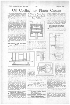
A Resume of Patent Spedfications that Have Recently Been Published PATENT No. 521,632 shows a scheme for cooling pistons of the larger sizes; that is, in the region of 4 ins. diameter. The patentee is Coventry Climax Engines. Ltd., and others, Friars Road, Coventry.
The scheme utilizes the engine lubricating oil as a cooling medium, the supply being pumped up a drilled connecting-rod and discharged, after circulating through the piston crown, into the sump, The piston proper is reduced in diameter at the top and the boss so formed is screwed to receive a crownpiece (2) which carries the ring grooves. The underside of the crown-piece is provided with a cast-in spiral groove (5).
which forms the cooling circuit. Oil arriving from the connecting-rod passes around a groove in the small-end bush and enters the hollow gudgeon-pin. From here it leaves via ports (3 and 4) and reaches the spiral groove (5). where it circulates towards the centre, where a port (1) allows its escape into the piston interior, whence it falls to the sump.
SEMI-TRAILER FOR ROAD-RAIL WORK
ls AANY road-rail transport schemes Mare found to be impracticable because of the need for special rail vehicles, and to abolish this need is the object of a system shown in patent No. 521,072by S.E.R.E.M., Marseilles, France. According to the patent, the chief difficulty is the height required between the rail-truck and the bottom of the transported vehicle, in other words, the space occupied by the wheels, and the object of the scheme is to avoid this.
The aim is achieved by using a semitrailer and shackling one end of the springs to a chain which, by means of a hand-operated sprocket, can allow the body to sink to the floor, as shown in the drawing. As there are no front wheels a simple jacking device is provided at the front end. Another feature of the patent is that the wheels are pivotally steerable, for ease in manceuvring when loading.
COMBUSTION SYSTEM TO LESSEN PRESSURE VARIATIONS A COMBUSTION system claimed to tA give a high mean effective pressure without excessive peaks of pressure is shown in patent No. 521,341 by E. Weber, 282, rue du Noyer, Brussels.
In this scheme, the combustion space is divided into two compartments, a double-curved recess (2) sunk in the head of the piston, and a spherical chamber (4) in the cylinder head. The latter is connected to the cylinder space by means of a tangential tapering passage (3).
The injector. located at point directs three streams of fuel, as clearly shown in the drawing. The quantity of fuel in each jet is made proportional to the volume of the chamber it serves; this feature is said to facilitate starting from cold.
A TWO-WAY EXPANDING PISTON-RING A PISTON-RING that can expand ft axially as well as radially is shown in patent No. 521,778, by F. Jones,
Moreton, Flat 1, New Road, Porthcawl. It shows a section of the ring in position; three elements go to make the assembly, a cylindef-engaging ring (1) and a pair of groove-abutting rings (2). The outward urge of the latter not only expands the cylinder ring, but also, by virtue of the sloping faces, produces a close fit in the groove. A spring-steel backing ring may be added if desired.
SUSPENSION SYSTEM WITH ADJUSTABLE COIL SPRINGS
ASIMPLE and robust' system for suspending a chassisism non-driven axles forms the subject of patent No.
521,753, by N.
Stra.ussier, Byron House, sSt. James's Street, London, S.W.1. The scheme has the additional advantage that it _permits the height of the chassis to be variable at will.
The wheels are
mounted on arms (1), which are pivoted on a cross-tube (5). The resilient members consist of heavy coil-springs (3), which are hooked in the wheel hubs and coiled around the cross-tube. The anchored ends are attached to blocks (6), which, being adjustable by the screws (4), allow the
, frame to be raised and lowered'.
Formed on the ends of the screws are squares to receive a key for rotating them.
:The swinging arms are also attached to a central torsion-rod (2), which affords some measure of stabilization to the system and serves also to retain the swinging arms on their tubular bearings. The scheme is said to be very _ suitable for use with turntable steering, owing to the low location of all the parts.