


Patents Completed.
Page 20
If you've noticed an error in this article please click here to report it so we can fix it.
Complete specifications of the following patents will be sent to any address in the United Kingdom upon receipt of eightpence per copy at the Sale Branch, Patent Office, Holborn, W.C.
SLIDE VALVE.—Lewis.—No. 16,957, dated 16th July, 1910.—According to this invention the valve is arranged between a cover removably attached te
the cylinder and an intermediate plate which is acted upon by the pressure in the cylinder to grip the valve between itself and the cover, The greater the pressure in the cylinder, the tighter is the joint between the working faces. This intermediate plate is provided with a throat piece which is free to elide in the cylinder port. If desired, packing may be arranged between the face of the throat piece and the ports. The outer face of the intermediate plate forms one of the valve seats, and against this the valve plate slides, DIFFERENTIAL GEAR—Renault.No. 15,539/1910, dated under International Convention 29th July, 1909.— According to the invention described in this specification, the drive is transmitted from the engine shaft, through two bevel pinions mounted on trunnions on the shaft, to other two pinions loose on the shaft. These latter engage large crown wheels mounted on short shafts fixed on opposite sides of the gear case ; these crown wheels are rigidly connected with pinions which drive spur wheels keyed on the ends of the shafts driving the road wheels, The advantages of this form of construction are that the device is strong and enables very strong teeth to he formed on the pinions without rendering the whole apparatus bulky. The members of the differential are mounted on the first shaft, that is to say, on the part which has the most rapid rotation ; these parts are therefore correspondingly lighter being subjected to smaller stress. Various forms of construction are fully described and illustrated in the specification, VALVE OPENER.—Brooke. — No. 5,880, dated 13th March, 1911.—The valve opener described in this specification is readily available for any kind of use, although its primary function is to hold open the inlet valve for convenience in starting heavy engines. A casing is provided for the lower part. of the valve rod or pusher, and a lever is mounted on this casing to engage with a suitable projecting piece on the valve rod. Suitable steps are provided by which the lever may be held in any position required. In one form the lever is made very thin and is springy enough to allow it to be pushed aside from the casing when it is not in use.
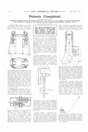
VALVE GEAR. — Lanehester.—No. 14.700, dated 18th June, 1910,—This invention relates to the sliding-sleeve type of valve, and provides a single sleeve to control both admission and exhaust. The inlet port is shown in the diagram entering on the left of the combustion chamber, and the exhaust port is some
what lower down on the right. The sleeve derives its motion from a lever which is rocked by two eccentrics, one of these eccentrics is driven at the engine speed
and the other from a half-speed shaft. The eccentrics are so set that the port in the sleeve will be opposite the exhaust port for a definite period ; the sleeve will then move rapidly and open the inlet port and then move to an intermediate position where the ports are covered by the packing rings during the compression and explosion strokes. The movement of the sleeve during this latter period is very slight.
HYDRAULIC JACK. — Doran and Taggart.—No. 1,284, dated 18th January, 1911.—The invention described in this specification relates to lifting jacks especially suitable for use when washing cars or cabs. The jack is operated by water obtained from the ordinary supply mains, the size of the piston being adapted to the pres sure of water at the main and the
weight to be lifted. The supply pipe
•
te the cylinder is arranged for use as a handle by which the jack is readily placed underneath the vehicle. A suitable valve having a bye-pass is used, so that the water is prevented from squirting Out around the nozzle when the hose is being attached.