


Switch for Protection Against Oil Failure
Page 40
If you've noticed an error in this article please click here to report it so we can fix it.
A Resume' of Recently Published Patent Specifications Obtainable from the Patent Office, Price is. each
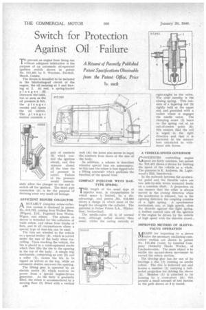
'TO prevent an engine from being run 1 without adequate lubrication is the purpose of an automatic oil-operated ignition switch shown in patent No. 515,461 by S. Wayman, Darthill, March, Cambs.
The device is intended to be included in the lubricating-oil circuit of the engine, the oil entering at 1 and leaving at 2. At rest, a spring-loaded plunger (5) obstructs the inlet, but so soon as the oil pressure is felt, the plunger recedes and opens the oil circuit. The plunger motion connects a pair of contacts (3) which control the ignition circuit, and this remains closed all the time the oil pressure is active. Failure of the pressure would immediately allow the plunger to rise and to switch off the ignition. The third pipe connection (4) is for the purpose of draining away any small oil leakage.
EFFICIENT REFUSE COLLECTOR
ANOTABLY complete refuse-collection system is disclosed in patent No. 513,782, coming from Walker Bros. (Wigan), Ltd., Pagefield Iron Works, Wigan, and others. The scheme as shown is intended for the collection of trade refuse, and refuse from blocks of flats, and in all circumstances where a special type of dust-bin can be used.
The bins are wheeled to the vehicle on a special trolley (3) , which is carried under the roar of the body when travelling. Upon reaching the vehicle, the bin is placed in a cable-operated cradle which then lifts the bin to the opening in the top of the body. A simple trip mechanism, comprising an arm (2) and a roller (1), causes the bin to be tipped on arrival at the top, while an automatic shutter uncovers the opening.
The lifting gear is operated by an electric motor (6). which receives its power from a special engine-driven generator. As the body is gradually filled, the refuse is accommodated by a moving floor (5) fitted with a vertical A30 wall (4); the latter also serves to expel the contents from doors at the rear of the body.
In addition, a scheme is described whereby special bins are unnecessary; in this case the refuse is first tipped into a lifting container which performs the function of the special bins.
COMPACT INJECTOR WITH BAR. TYPE SPRING
THE length of the usual type of injector may, in circumstances in which space is limited, be a disadvantage, and patent ,No. 515,064 shows a design in which most of the length lies alongside the cylinder. The patentee is Sulzer Freres S.A., Winterthur. Switzerland.
The needle-valve (2) is of normal form, although rather shorter than usual, whilst the casing extend k at right-angles to the valve. The chief novelty is the closing spring. This consists of a tapering rod (3) rigidly held at the upper end and provided with a socket where it engages the needle valve. The clamping screw (1) bears on the spring rod at an out-of-centre point (4); this ensures that the rod is urged in the right direction and that it is anchored in the manner best calculated to withstand side forces.
A VEHICLE-SPEED GOVERNOR
GOVERNORS controlling engine speed are fairly common, but patent No. 515,431 shows a device for limiting the speed of the vehicle as a whole. The patentee is E. Andrews, 34, Lightwood's Hill, Smethwick,
In the rodwork between the accelerator pedal and the throttle valve are two side-by-side levers mounted freely on a common shaft. A projection on one ensures that the other is always moved in the closing direction when the accelerator is released, but in the opening direction the coupling consists of a light spring. A speedometer mechanism can, at high speeds, close the throttle against the light spring. A further control cuts off the ignition if the engine be driven by the vehicle at high speed with the throttle closed..
IMPROVED METHOD OF SLEEVE. VALVE OPERATION /VANS for imparting to a sleeve 1V1valve the necessary oscillating-cumrotary motion are shown in patent No. 515,404 (void) by Limited Company (formerly Skoda Works), of Czechoslovakia. The main object is to enable the up-and-down movement to exceed the rotary motion.
The driving gear has for one of its bearings a disc (5) running on needle rollers. The disc is hollowed out and houses a member (1) carrying a ballended projection for driving the sleeve (2). Member (1) is attached to its housing by a cross-pivot (4); this permits a small amount of lost motion so the path shown at 3 is traced.