


Patents Completed.
Page 22
If you've noticed an error in this article please click here to report it so we can fix it.
Complete specifications of the following patents will be sent to any address in the United Kingdom upon receipt of eightpence per copy at the Sale Branch, Patent Office, Holborn, W.C.
CA RBURETTER.—Sm ith.—No. 1,075, dated 15th January, 1909.—The object of this invention is to maintain a constant proportion of fuel and air at all speeds of the engine. The float chamber (A) communicates with the fuel nozzle within the mixing chamber (B), as usual. The fuel nozzle (C) is provided with a small orifice which is adapted to be covered or uncovered by a cap (CI) that fits closely over the fuel nozzle. This cap has a similar orifice which registers with the orifice in the fuel nozzle when the throttle valve is fully open. At each side of the mixing chamber (B) a cylindrical extension is formed, in which is mounted a sleeve capable of rotation ; this sleeve is formed with an opening which establishes communication between the mixing chamber and the interior of the cylindrical extension. These extensions constitute the air inlet and the outlet for the mixture, and the area of the
openings communicating with the mixing chamber can be adjusted by turning the sleeves therein. The throttle is constituted by a hollow piston (D), which slides within the mixing chamber (13). This piston is provided with two openings at opposite points in the walls thereof, and these communicate with the air inlet and the induction conduit respectively, when the piston valve is in its lower position. When, however, the piston valve is raised, both ihe inlet and the induction-pipe openings are closed, except for small openings (1)3) provided in the lower portion of the walls of the throttle (D). 'rhe cap covering the fuel nozzle is formed with spiral grooves, which are engaged by crojections formed on a ring secured to the lower end of the throttle valve. The arrangement is such that, when the throttle valve is fully open, the orifice in the cap registers with the orifice in the fuel nozzle, but en the throttle valve being raised, as when closing the latter, the cap will be rotated and the fuel will be shut off.
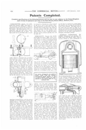
FIRE Dennis.—No. 13,541, dared 28th December, 1908.—This invention relates to motor-driven firc engines of the type in which a centrifugal pump driven by a propelling motor is employed. On the engine shaft, between the clutch and the change gear, a spur wheel is mounted which gears with a similar spur wheel mounted on another shaft arranged above. This latter shaft drives a centrifugal pump situated at the rear of the vehicle. Either of the spur wheels may be slidahle on their respective shafts to connect or disconnect the pump with the engine, or a clutch may be employed for this purpose. The present invention has particular reference to means for charging the pump. A water tank (A) is arranged at the rear of the
vehicle, and this tank supplies water through a pipe (AI) to the pump. The pump (13) has the usual delivery pipes (C) and a supply or suction pipe in which is arranged a non-return valve (D1). At the supply side of the non-return valve, a pipe is connected which leads to an injector (E) mounted on the top of the tank (A), this pipe being controlled by a valve (El). The delivery side of the pump is also connected to the injector (E) by means of a pipe (F) which is controlled by a valve (Fl). When starting the pump, the valves in the delivery pipes (C) are closed, and thi.s. valves (El, Fl) are opened. This will allow the injector (E) to operate, and the air within tha supply pipe will be quickly exhausted. As soon as the water has reached the top of the suction, which
can be seen by means of a water gauge, the injector may be shut off and the delivery valves opened. The same water in the tank may be used as often as required, as it will be seen that this is only circulated and is not used for flooding the suction or for any other usual method of charging centrifugal pumps.
TNTERNAL COMBUSTION ENGINES.—Drummond and Another, No. 6,060, dated 13th March, 1909.—This invention relates to valve mechanism of the reciprocating-sleeve type. The head of the working cylinder is bored transversely to form a cylindrical hole, one end of which communicates with the exhaustand the other end with the inlet or induction pipe. This hole communi cates with the main cylinder by means of a port formed in the head thereof, through which the fuel is admitted and exhausted from the working cylinder. Within the cylindrical hole, a liner is securely fixed which has a number of ports corresponding to the port provided in the cylinder head. Within the liner, a reciprocating sleeve is arranged, and within this sleeve is a reciprocating hollow piston ; both of these are provided with ports which are adapted to register with the ports in the. cylinder at the proper moment. The reciprocating sleeve and the reciprocating hollow piston are operated by eccentrics or cranks through tin medium of suitable connecting rods. The object of the liner is to protect the sliding sleeve from the heat of the exhaust gases.